
Users Manual Part 2

SIM8260A_Hardware Design_V1.05
www.simcom.com 74 / 122
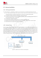
4.2 Antenna Installation
4.2.1 PCB Layout Guidelines
To avoid interference, minimalize the insertion loss of the RF trace, the PCB should follow below rules:
The coaxial cable PCB pads, RF antenna connector and other connectors which used to test
contact performance of module should place as close as to the module antenna pads.
The antenna matching network should place to antenna feed port.
The RF trace should be as short and straight as possible, and do not routing as perpendicular line,
we recommend do it as 45
°
corner trace.
The RF traces should be grounded.
RF device should place grounding wire on the nearest grounding surface.
Between RF trace and below should avoid other signal trace or parallel trace to the RF signal.
Recommend to more ground vias near the RF traces.
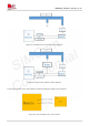
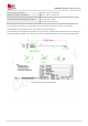
4.2.2 Antenna Tuner
When the device supports 700MHz low frequency(B12\B13\B28), it is recommended to add antenna tuner
to improve RF performance. Antenna tuner contains antenna aperture tuner, antenna impedance tuner an
d hybrid tuner of the two. Aperture tuning optimizes the total antenna efficiency from the free space of the
antenna terminal, and can optimize antenna efficiency across multiple frequency bands. Impedance tuner
adjusts the mismatch between the RF front end and the antenna to achieve maximum transmission power.
Hybrid tuner combines the advantages of the two to maximize antenna RF performance. Customers can
choose according to specific needs, according to the recommendations from the antenna vendor.
Figure 43: Aperture tuner reference block diagram