
Users Manual Part 2

SIM8260A_Hardware Design_V1.05
www.simcom.com 68 / 122
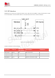
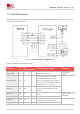
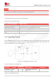
The value of the resistor R1 depends on the LED characteristics.
The timing parameters are shown in the following table.
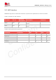
Table 47: NET_STATUS pin status
NET_STATUS pin status
Module status
Always On
Searching network; call connection (including 5G, VOLTE)
100ms ON, 100ms OFF
5G Data transmitting; 5G registered on network
200ms ON, 200ms OFF
3G/4G Data transmitting; 4G registered on network
800ms ON, 800ms OFF
3G registered on network
OFF
Power off; in sleep mode
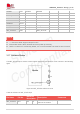
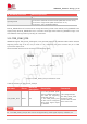
3.18 Flight Mode Control
The W_DISABLE pin can be used to control SIM8260A to enter or exit the flight mode. In flight mode, the
RF circuit is closed to prevent interference with other equipment’s and minimize current consumption. Its
reference circuit is shown in the following figure.
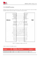
Figure 40: W_DISABLE pin reference circuit
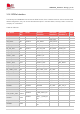
Table 48: Definition of W_DISABLE pin
Pin Name
Pin No.
Electrical
Description
Description
Comments
W_DISABLE
AG1
DI
P3
Flight mode control input
active low
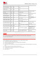
Table 49: W_DISABLE pin status
NOTE