
Users Manual Part 2

SIM8260A_Hardware Design_V1.05
www.simcom.com 59 / 122
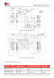
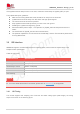
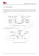
Figure 35: UART RX level conversion circuit
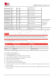
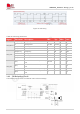
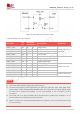
Table 39: Definition of UART interface
Pin name
Pin
no.
Electrical
description
description
Comment
UART1_CTS
AA1
DI
P3
Clear to send
Default use for AT
command
UART1_RTS
AC1
DO
P3
Request to send
UART1_TXD
AB3
DO
P3
Transmit data
UART1_RXD
AD3
DI
P3
Receive data
UART1_DCD
W5
DO
P3
Carrier detect
UART1_RI
AA5
DO
P3
Ring indicator
UART1_DTR
AC5
DI
P3
Data terminal ready
BT_UART_CTS
R5
DI
P3
Clear to send
Default use for BT
BT_UART_RTS
U5
DO
P3
Request to send
BT_UART_TXD
T7
DO
P3
Transmit data
BT_UART_RXD
V7
DI
P3
Receive data
DBG_UART_RXD
L5
DI
P3
Receive data
Used for debug only
DBG_UART_TXD
N5
DO
P3
Transmit data
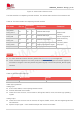
The 4-wire UART interface support flow control function.
The baud rate frequency band supported by the serial port: 300, 600, 1200, 2400, 4800, 9600,
19200, 38400, 57600,115200,203400,460800,921600. The UART rate is as high as 4MHZ. When
the baud rate is greater than 460bps, it is not recommended to use a transistor for level
conversion.
The UART rate is as high as 4MHZ. When the baud rate is greater than 460Kbps, it is not
recommended to use a transistor for level conversion.
UART1 is used as AT command and DTR detection by default, it is not recommended to be used
for other functions
NOTE