
Specifications


SIM7912&SIM7906 Hardware Design V1.02
www.simcom.com 57 / 85
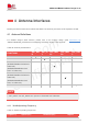
4.1.2 GNSS Frequency
The following table shows frequency specification of GNSS antenna interface.
Table 39: GNSS frequency
Type
Frequecy
GPS L1/Galileo/QZSS
1575.42±1.023MHz
GPS L5
1176.45±10.23MHz
GLONASS
1597.5~1605.8MHz
BeiDou/Compass
1561.098±2.046MHz
4.2 Antenna Installation
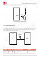
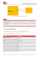
4.2.1 PCB Layout Guidelines
To avoid interference, minimalize the insertion loss of the RF trace, the PCB should follow below rules:
(1) The coaxial cable PCB pads, RF antenna connector and other connectors which used to test
contact performance of module should place as close as to the module antenna pads.
(2) The antenna matching network should place to antenna feed port.
(3) The RF trace should be as short and straight as possible, and do not routing as perpendicular line,
we recommend do it as 45° corner trace.
(4) And the RF trace ground should be complete;
(5) RF device should place ground to the nearest ground plane;
(6) Between RF trace and below should avoid other signal trace or parallel trace to the RF signal.
(7) Recommend to more ground vias near the RF traces.
4.2.2 Antenna Tuner
When end device needs to support 700MHz low frequency(B12\B13\B28), it is recommended to add anten
na tuner to improve RF performance. Antenna tuner contains antenna aperture tuner, antenna impedance
tuner and hybrid tuner of the two. Aperture tuner optimizes the total antenna efficiency from the free space
of the antenna terminal, and can optimize antenna efficiency across multiple frequency bands. Impedance
tuner adjusts the mismatch between the RF front end and the antenna to achieve maximum transmission
power. Hybrid tuner combines the advantages of both to maximize antenna RF performance. Customers c
an choose according to specific needs, according to the recommendations from the antenna vendor.