
Specifications


SIM7912&SIM7906 Hardware Design V1.02
www.simcom.com 52 / 85
Table 33: W_DISABLE pin status
W_DISABLE pin status
Module operation
Input low level
Flight mode: RF is disabled
Input high level
AT+CFUN=4: Flight mode
AT+CFUN=1: RF is enabled (Default)
3.18 USB_BOOT Interface
Module provides a USB_BOOT pin. Pulling up USB_BOOT to VDD_EXT before power-on will make the
module enter emergency download mode when powered on. In this mode, the module supports firmware
upgrade over USB interface.
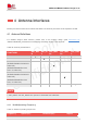
Table 34: Pin Definition of USB_BOOT Interface
Pin name
Pin no.
I/O
Functional description
Comment
USB_BOOT
140
DI
Force the module into emergency
download mode
1.8V power domain.
Active high.
If unused, keep it open.
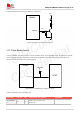
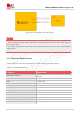
The following figure shows a reference circuit of USB_BOOT.
Module
VDD_EXT
USB_BOOT
10K
Close to
module
Test points
Figure 30: Reference Circuit of USB_BOOT
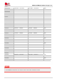
3.19 Antenna Tuner Control Interface*
The module supports external antenna tuner control through either RFFE interface or dedicated GPIO
interfaces. Customers can choose either one according to their tuner design. The following are the pin
definitions of the RFFE and dedicated GPIO interfaces.