
Specifications


SIM7912&SIM7906 Hardware Design V1.02
www.simcom.com 36 / 85
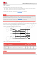
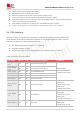
Gap from other signals keeps 4xline width.
Gap between Rx-to-Tx keeps 4xline width.
External components should be placed near the USB connector.
Trace routes away from other sensitive signals (RF, especially 2.4 GHz).
Route differential pairs in the inner layers with a solid GND reference to have good impedance
control and to minimize discontinuities.
Keep isolation between the Tx pair, Rx pair, and DP/DM to avoid crosstalk.
If core vias are used, use no more than two core vias per signal line to limit stubs.
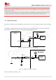
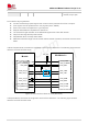
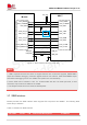
3.6 PCIe Interface
Module provides one integrated PCIe (Peripheral Component Interconnect Express) interface which
complies with the PCI Express Specification, Revision 2.1 and supports 5Gbps per lane. The PCIe
interface of module is only used for data transmission
PCI Express Specification Revision 2.1 compliance
Data rate at 5Gbps per lane
Can be used to connect to an external Ethernet IC (MAC and PHY) or WLAN IC
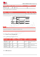
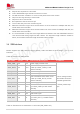
Table 16: Definition of PCIe interface
Pin name
Pin no.
I/O
Functional description
Comment
PCIE_REFCL
K_P
179
AIO
PCIe reference clock plus
Required 90Ω
differential impedance
If unused, keep it open.
PCIE_REFCL
K_M
180
AIO
PCIe reference clock minus
PCIE_TX_M
182
AO
PCIe transmit0 minus
PCIE_TX_P
183
AO
PCIe transmit0 plus
PCIE_RX_M
185
AI
PCIe receive0 minus
PCIE_RX_P
186
AI
PCIe receive0 plus
PCIE_CLK_R
EQ_N
188
IO
PCIe clock request
In master mode, it is an
input signal.
In slave mode, it is an
output signal.
If unused, keep it open.
PCIE_WAKE
_N
190
IO
PCIe wake-up
In master mode, it is an
input signal.
In slave mode, it is an
output signal.
If unused, keep it open.
PCIE_RST_N
189
IO
PCIe reset
In master mode, it is an
output signal.
In slave mode, it is an