
Specifications


SIM7912&SIM7906 Hardware Design V1.02
www.simcom.com 28 / 85
The customer’s PCB design must have a solid ground plane throughout the board as the primary
reference plane for most signals.
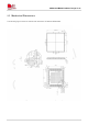
3.1.2 Recommended Power Supply Circuit
It is recommended to use a switching mode power supply or a linear regulator power supply. Make sure it
can provide the current up to 3A at least.
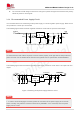
The following figure shows the linear regulator reference circuit with 5V input and 3.8V output.
Vin
Vout
GND
ADJ
3
+
PWR_CTRL
R2
R1
VBAT
100K(1%)
47K(1%)
+
U1
MIC29502WU
5
4
1
2
C1 C2
100uF
1uF
DC INPUT
R3
470R
EN
FUSE
C3
330uF
C4
100nF
Figure 6: Linear regulator reference circuit
An extra minimum load of R3 is required, to ensure it work properly under light load in sleep mode and
power off mode. For the details about minimum load, please refer to specification of MIC29502WU.
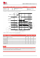
The following figure shows the switching mode power supply reference circuit with 5~12V input and 3.8V
output.
10uF
EN
IN LX BS
GND
FB
VBAT
DC INPUT
PWR_CTRL
10uF
10uF
100nF
L101
VLS5045EX-3R3N
3.3UH
160K 1%
100nF
100pF
22uF 10uF
30K 1%
C1
C2 C3
C4
C5
R3
R4
C6
C8 C9
U1
SY8105IADC
Fuse
FB1
UPZ1608E300-5R0TF
30ohm@100MHz
1
6
54
2
3
Figure 7: Switching mode power supply reference circuit
1. In order to avoid damaging the module, please do not switch off the power supply when module
works normally. Only after the module is shut down by PWRKEY or AT command, then the power
supply can be cut off.
NOTE
NOTE