
Specifications


SIM7912&SIM7906 Hardware Design V1.02
www.simcom.com 42 / 85
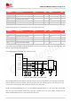
Using “AT+SMSIMCFG=1,1” and “AT+SMSIMCFG=1,2” AT command to switch SIM1 and SIM2 function,
for more details, please refer to
Document [1] in the appendix.
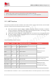
The following table shows recommended TVS of ESD protect and SIM socket.
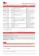
Table 21: Recommended TVS and SIM socket list
Name
Manufacturer
Model
TVS
ST
ESDA6V1-5W6
SIM socket
MUP
MUP-C792-3
If the SIM card hot-swap function is not used, customers should keep the SIM_DET pin open.
1. The recommended SIM socket is normal close, which makes SIM_DET is active high. If the active
low of SIM_DET is required, SIM socket should be normal open.
2. AT command “AT+UIMHOTSWAPLEVEL” could change the SIM_DET detection level and the
default value is 1, which is active high, for more details, please refer to Document [1] in the appendix.
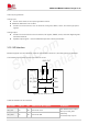
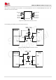
The SIM card layout guidelines:
Make sure that the SIM card socket should be far away from the antennas.
SIM traces should be away from RF, VBAT and high-speed signals.
The traces should be as short as possible.
Keep SIM socket’s GND pins directly connect to the main ground.
Shielding the SIM card signals by ground.
Recommended to place a 33pF~1uF capacitor on SIM_VDD net and place close to the holder.
The rise/fall time of SIM_CLK should not exceed 40ns.
The parasitic capacitance of TVS should not exceed 60pF, and the TVS should be placed close to
the SIM socket.
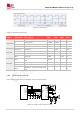
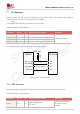
3.9 PCM and I2S Interface
Module supports one I2S/PCM interface for external codec, which meets the requirements in the Phillips
I2S bus specification.
The PCM interface is multiplexing with I2S interface. The default audio interface of the module is I2S.
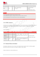
Table 22: The PCM interface is multiplexing with I2S interface
NOTE