
Specifications


SIM7912&SIM7906 Hardware Design V1.02
www.simcom.com 41 / 85
Symbol
Parameter
Min.
Typ.
Max.
Unit
SIM_VDD
Power supply for SIM card
1.65
1.8
1.95
V
V
IH
High-level input voltage
1.26
-
1.95
V
V
IL
Low-level input voltage
0
-
0.36
V
V
OH
High-level output voltage
1.44
-
1.8
V
V
OL
Low-level output voltage
0
-
0.4
V
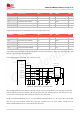
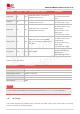
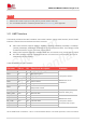
Table 20: SIM electronic characteristics 3.0V mode (SIM_PWR=3.0V)
Symbol
Parameter
Min.
Typ.
Max.
Unit
SIM_VDD
Power supply for SIM card
2.7
3.0
3.05
V
V
IH
High-level input voltage
2.1
-
3.05
V
V
IL
Low-level input voltage
0
-
0.6
V
V
OH
High-level output voltage
2.4
-
3.0
V
V
OL
Low-level output voltage
0
-
0.4
V
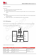
The module supports SIM card hot-swap function through the SIM_DET pin, which is a level trigger pin. The
SIM_DET pin requires pull up externally.
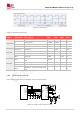
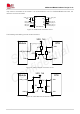
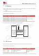
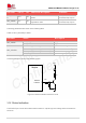
The following figure shows SIM card reference circuit.
TVS
(U)SIM_VDD
(U)SIM_CLK
(U)SIM_DATA
(U)SIM_RST
0Ω
220nF
(U)SIM Socket
MUP-C792-3
0Ω
0Ω
(NC)
100Ω
(U)SIM_DET
33pF
GND1
GND1
CD1
CD1
Module
(NC) (NC) (NC)
VCC
RST
CLK
GND
VPP
I/O
VDD_EXT
470KΩ
Figure 19: SIM interface reference circuit
After inserting SIM card, the SIM_DET pin will change from low to high level. The rising edge will indicate
that the SIM card has been inserted. After removing the SIM card, the SIM_DET pin will change from high
to low level. This falling edge will indicate the removal of the SIM card.
Using “AT+UIMHOTSWAPON=0 or 1” and “AT+UIMHOTSWAPLEVEL=0 or 1”AT command to set module
SIM card hot swap function enable and SIM card detection level, for more details, please refer to
SIM7912&SIM7906 Series AT Command Manual document.