
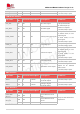
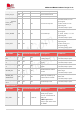
Specifications


SIM7912&SIM7906 Hardware Design V1.02
www.simcom.com 29 / 85
2. It is suggested that customer's design should have the ability to switch off the power supply for
module in abnormal state, and then switch on the power to restart the module.
3. The PWR_CTRL signal recommend connect to the host and can be controlled.
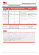
3.1.3 Voltage Monitor
To monitor the VBAT voltage, the AT command “AT+CBC” can be used.
For more details about voltage monitor commands, please refer to Document [1] in the appendix.
3.2 Power On and Off Module
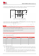
3.2.1 Power On
Drive the PWRKEY pin to a low level
and hold it for 1 seconds, then release, the module will be powered
on. This pin is already pulled up internally. The electrical characteristics are listed in Table 10, and the
following figure shows the power on circuit.
PWRKEY
1K
Module
PMU
1s
PWRKEY
Figure 8: Power on the module use button
1K
Module
PMU
PWRKEY
≥1s
GPIO
MCU
Figure 9: Power on the module use GPIO drive
Table 9: Definition of PWRKEY pin
NOTE