
Specifications


SIM7912&SIM7906 Hardware Design V1.02
www.simcom.com 24 / 85
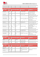
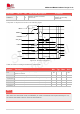
RFFE_DATA
73
DIO
P3
external tuner control
If unused, keep it open.
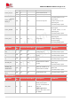
Antenna interface
Pin name
Pin
No.
Electrical description
Description
Comment
ANT_MAIN
107
AIO
Main antenna interface
supporting all bands
50Ω impedance
ANT_DIV
127
AI
RXD antenna interface
supporting all bands
50Ω impedance
If unused, keep them
open.
ANT_ MIMO1
101
AI
4×4 MIMO antenna
interface supporting all
bands
50Ω impedance
If unused, keep them
open.
ANT_MIMO2
113
AI
4×4 MIMO antenna
interface supporting all
bands
50Ω impedance
If unused, keep them
open.
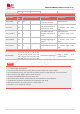
ANT_GNSS
119
AI
GNSS antenna interface
50Ω impedance
If unused, keep them
open.
RESERVED interface
RESERVED
4, 6~9, 11, 12, 14, 15, 18, 19, 20,
21, 22, 23, 72, 91, 95, 134, 176,
192, 193, 194, 195, 197, 198, 199,
200, 201, 210, 211, 212, 213, 300
Reserved for future use
Keep these pins
unconnected.
1. “*” means under development.
2. The I2C signals need pull up to VDD_EXT by 2.2K resistors out of the module.
3. If not use SDIO function, the VDD_P2 pin should connect to VDD_EXT pin out of the module.
4. Do not pull up USB_BOOT during normal power up.
5. Unused and RESERVED pins should keep open.
6. Recommend ESD protect components out of the module for used interfaces.
7. All GND pins should be connected to the customer’s main PCB.
8. GPIO2 will become low level when the module starts up.
9. Pin 209 in V1.01 module is reserved.
NOTE