
User's Manual
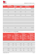
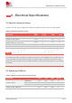
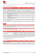
Table Of Contents
- 1.Introduction
- 2.Package Information
- 3.Interface Application
- 4.RF Specifications
- 5.Electrical Specifications
- 6.SMT Production Guide
- 7.Packaging
- 8.Appendix

SIM7075G User Manual V1.00
www.simcom.com 48 / 74
5. Electrical Specifications
5.1 Absolute maximum ratings
Absolute maximum rating for digital and analog pins of SIM7075G are listed in the following table:
Table 30: Absolute maximum ratings
Parameter
Min.
Typ.
Max.
Unit
Voltage on VBAT
-0.3
-
6.0
V
Voltage on USB_VBUS
-0.3
-
6.0
V
Voltage at digital pins
(RESET,GPIO,I2C,UART,PCM)
-0.3
-
2.1
V
Voltage at PWRKEY
-0.3
-
2.1
V
ADC
-0.3
-
1.875
V
The absolute parameter is tested when VBAT has the power but the PWRKEY has no pulled down. If it
is over the range, the module will be damage. If the power supply on VBAT pin had been shut down,
and the other pin should not have the voltage. Otherwise, it may lead to abnormally boot up or damage
the module.
5.2 Operating conditions
Table 31: Module recommended operating ratings
Parameter
Min.
Typ.
Max.
Unit
Voltage at VBAT
SIM7070G
3.0
3.8
4.6
V
SIM7070E
3.2
3.8
4.2
V
SIM7070G-NG
3.0
3.8
4.6
V
Voltage at USB_VBUS pin
3.5
5.0
5.25
V
NOTE