
User's Manual
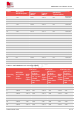
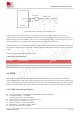
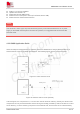
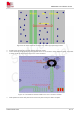
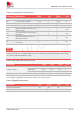
Table Of Contents
- 1.Introduction
- 2.Package Information
- 3.Interface Application
- 4.RF Specifications
- 5.Electrical Specifications
- 6.SMT Production Guide
- 7.Packaging
- 8.Appendix

SIM7075G User Manual V1.00
www.simcom.com 43 / 74
Figure 26: Antenna matching circuit (MAIN_ANT)
In above figure, the components R1, C1, C2 and R2 are used for antenna matching, the values of
components can only be achieved after the antenna tuning and usually provided by antenna vendor. By
default, the R1, R2 are 0Ω resistors, and the C1, C2 are reserved for tuning. The component D1 is a TVS
for ESD protection, and it is optional for users according to application environment.
The RF test connector is used for the conducted RF performance test, and should be placed as close as to
the module
’
s MAIN_ANT pin. The traces impedance between SIM7075G and antenna must be controlled
in 50Ω.
Two TVS are recommended in the table below.
Table 29: Recommended TVS
Package
Part Number
Vender
0201
CE0201S05G01R
硕凯
0402
PESD0402-03
PRISIMI
4.3 GNSS
SIM7075G merges GNSS (GPS/GLONASS/BD/Galileo) satellite and network information to provide a
high-availability solution that offers industry-leading accuracy and performance. This solution performs well,
even in very challenging environmental conditions where conventional GNSS receivers fail, and provides a
platform to enable wireless operators to address both location-based services and emergency mandates.
4.3.1 GNSS Technical specification
Tracking sensitivity: -159 dBm (GPS+GLONASS)/-159 dBm (GPS+BD)
Cold-start sensitivity: -147.5 dBm
Accuracy (Open Sky): 0.4 m(GPS+BD)
TTFF (Open Sky) : Hot start < 1 s, Cold start< 31 s
Receiver Type: 16-channel, C/A Code
GPS L1 Frequency: 1575.42±1.023MHz
GLONASS L1: 1598.0625 ~1605.375MHz
BDS B1: 1559.052~1591.788MHz