
User's Manual
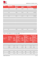
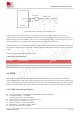
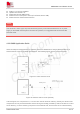
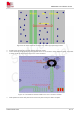
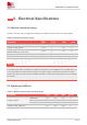
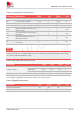
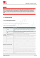
Table Of Contents
- 1.Introduction
- 2.Package Information
- 3.Interface Application
- 4.RF Specifications
- 5.Electrical Specifications
- 6.SMT Production Guide
- 7.Packaging
- 8.Appendix

SIM7075G User Manual V1.00
www.simcom.com 42 / 74
18
-108.2
-114.9
-129
-114.9
-129
-114.9
-129
19
-108.2
-115.1
-128
-115.1
-128
-115.1
-128
20
-108.2
-114.1
-128
-114.1
-128
-114.1
-128
25
-108.2
-114.6
-130
-114.6
-130
-114.6
-130
26
-108.2
-114.6
-129
-114.6
-129
-114.6
-129
28
-108.2
-115.9
-130
-115.9
-130
-115.9
-130
31
-108.2
-114.7
-129
66
-108.2
-114.8
-129
-114.8
-129
-114.8
-129
71
-108.2
-114.4
-129
-114.4
-129
The 12/7/1/128 of the REFSENS Typical Repeated 12/ 7/1/128 means Subcarriers=12, MCS.TBS=7,
#SF/#RU=1, #Repetition=128.
4.2 LTE Antenna Design Guide
Users should connect antennas to SIM7075G antenna pads through micro-strip line or other types of RF
trace and the trace impedance must be controlled in 50Ω. SIMCom recommends that the total insertion loss
between the antenna pads and antennas should meet the following requirements:
Table 28: Trace loss
Frequency
Loss
700MHz-960MHz
<0.5dB
1710MHz-2170MHz
<0.9dB
2300MHz-2650MHz
<1.2dB
To facilitate the antenna tuning and certification test, a RF connector and an antenna matching circuit
should be added. The following figure is the recommended circuit.
NOTE