
User's Manual
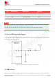
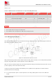
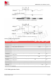
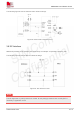
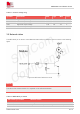
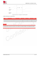
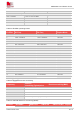
Table Of Contents
- 1.Introduction
- 2.Package Information
- 3.Interface Application
- 4.RF Specifications
- 5.Electrical Specifications
- 6.SMT Production Guide
- 7.Packaging
- 8.Appendix

SIM7075G User Manual V1.00
www.simcom.com 33 / 74
Place TVS near the SIM card holder. The junction capacity of the TVS should not exceed 50pF. The
22Ω resistor in series between the SIM card holder and the module can enhance the ESD protection
performance.
Keep SIM card signals away from RF and VBAT traces.
SIM card signal line traces to avoid branch.
To avoid cross-talk between SIM_DATA and SIM_CLK, keep them away from each other and shield
them with surrounded ground. USIM_RST should also be ground shielded.
3.7 PCM Interface
SIM7075G provides a PCM interface for external codec, which can be used in master mode with short sync
and 16 bits linear format.
Table 15: PCM format
Characteristics
Specification
Line Interface Format
Linear(Fixed)
Data length
16bits(Fixed)
PCM Clock/Sync Source
Master Mode(Fixed)
PCM Clock Rate
2048 KHz (Fixed)
PCM Sync Format
Short sync(Fixed)
Data Ordering
MSB
For more details about PCM AT commands, please refer to document [1].
3.7.1 PCM timing
SIM7075G supports 2.048 MHz PCM data and sync timing for 16 bits linear format codec.
Figure 19: PCM_SYNC timing
NOTE