
User's Manual
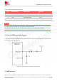
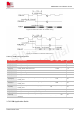
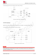
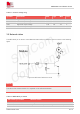
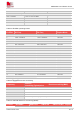
Table Of Contents
- 1.Introduction
- 2.Package Information
- 3.Interface Application
- 4.RF Specifications
- 5.Electrical Specifications
- 6.SMT Production Guide
- 7.Packaging
- 8.Appendix

SIM7075G User Manual V1.00
www.simcom.com 32 / 74
value is 1.8V.
Table 14: SIM electronic characteristic in 1.8V mode (SIM_VDD=1.8V)
Symbol
Parameter
Min.
Typ.
Max.
Unit
SIM_VDD
LDO power output voltage
1.75
1.8
1.95
V
VIH
High-level input voltage
0.65*SIM_VDD
-
SIM_VDD +0.3
V
VIL
Low-level input voltage
-0.3
0
0.35*SIM_VDD
V
VOH
High-level output voltage
SIM_VDD -0.45
-
SIM_VDD
V
VOL
Low-level output voltage
0
0
0.45
V
1. The module does not support 3V SIM card.
2. The software does not support the SIM card hot swap function.
3.6.1 SIM Application Guide
Note that the SIM peripheral circuit should be close to the SIM card socket. The following figure shows the
6-pin SIM card holder reference circuit.
Figure 18: SIM interface reference circuit
SIM_DATA has been pulled up with a 20KR resistor to SIM_VDD in module, so it no need pulled up resistor
anymore. SIM_VDD needs a 100nF capacitor close to SIM socket.
SIM_CLK is very important signal, the rise time and fall time of SIM_CLK should be less than 40ns. So the
junction capacity of the TVS need to less 50pF.
In order to enhance the reliability and availability of the (U)SIM card in applications. Please follow the
guidelines below when designing.
It is recommended to place a 100nF capacitor on the SIM_VDD signal line close to the SIM card
holder.
NOTE