User's Manual
Manuals
Brands
SIMCom Manuals
Electronics
LPWA Module
1
2
3
4
5
6
7
8
9
10
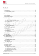
Table Of Contents
1.Introduction
1.1 Product Outline
1.2 Hardware Interface Overview
1.3 Hardware Block Diagram
1.4Functional Overview
2.Package Information
2.1 Pin Assignment Overview
2.2 Pin Description
2.3 Mechanical Information
2.4 Footprint Recommendation
3.Interface Application
3.1 Power Supply
3.1.1 Power Supply Design Guide
3.1.2 Recommended Power Supply Circuit
3.1.3Voltage Monitor
3.2 Power on/Power off Function
3.2.1 Power on
3.2.2 Power off
3.3 UART Interface
3.3.1 UART Design Guide
3.3.2 RI and DTR Behavior
3.4 USB Interface
3.5 Force USB Download Interface
3.6 SIM Interface
3.6.1 SIM Application Guide
3.7 PCM Interface
3.7.1 PCM timing
3.7.2 PCM Application Guide
3.8 I2C Interface
3.9 Network status
3.10 ADC interface
3.11 LDO output
4.RF Specifications
4.1 LTE RF Specifications
4.2 LTE Antenna Design Guide
4.3 GNSS
4.3.1 GNSS Technical specification
4.3.2 GNSS Application Guide
4.4 RF traces note
4.4.1 RF traces layout
4.4.2 LTE ANT and other system ANT decoupling
5.Electrical Specifications
5.1 Absolute maximum ratings
5.2 Operating conditions
5.3 Operating Mode
5.3.1 Operating Mode Definition
5.3.2 Sleep mode
5.3.3 Minimum functionality mode and Flight mode
5.3.4 Power Saving Mode (PSM)
5.3.5 Extended Mode DRX (e-DRX)
5.4 Current Consumption
5.5 ESD Notes
6.SMT Production Guide
6.1 Top and Bottom View of SIM7075G
6.2 Label Information
6.3 Typical SMT Reflow Profile
6.4 Moisture Sensitivity Level (MSL)
6.5 Baking
6.6 Stencil Foil Design Recommendation
7.Packaging
7.1 Tray packaging
8.Appendix
A. Reference Design
B. Design check list
C. Coding Schemes and Maximum Net Data Rates over
D. Related Documents
E. Terms and Abbreviations
F. Safety Caution
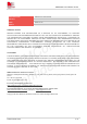
SIM7075G
User
Manual
V1.00
ww
w.simcom.com
3
/
74
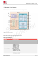
V
ersion
History
Date
V
ersion
Description
of
ch
ange
Author
2022-05-23
1.00
Original
Y
anping
Y
ang
Meihao
Li
1
2
3
4
5
...
...
74