
User's Manual
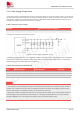
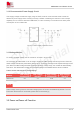
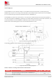
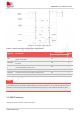
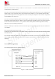
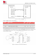
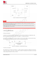
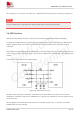
Table Of Contents
- 1.Introduction
- 2.Package Information
- 3.Interface Application
- 4.RF Specifications
- 5.Electrical Specifications
- 6.SMT Production Guide
- 7.Packaging
- 8.Appendix

SIM7075G User Manual V1.00
www.simcom.com 26 / 74
Figure 10: Power off timing sequence
Table 11: Power off timing and electronic characteristic
Symbol
Parameter
Time value
Unit
Min.
Typ.
Max.
Toff
The active low level time pulse on PWRKEY pin to
power off module
1.2
-
-
s
Toff(vdd)
The time from power-off issue to VDD_EXT pin output
low level
1.8
-
-
s
Toff(status
)
The time from power-off issue to STATUS pin output
low level(indicating power off )*
1.8
-
-
s
Toff(uart)
The time from power-off issue to UART port off
1.8
-
-
s
Toff(usb)
The time from power-off issue to USB port off
1.8
-
-
s
Toff-on
The buffer time from power-off issue to power-on issue
2
-
-
s
The STATUS pin can be used to detect whether module is powered on or not. When module has been
powered on and firmware goes ready, STATUS will be high level, or else STATUS will still low level.
3.3 UART Interface
SIM7075G can provide 3channels serial ports:
NOTE