
User's Manual
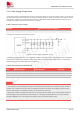
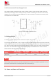
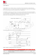
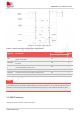
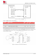
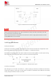
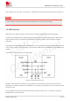
Table Of Contents
- 1.Introduction
- 2.Package Information
- 3.Interface Application
- 4.RF Specifications
- 5.Electrical Specifications
- 6.SMT Production Guide
- 7.Packaging
- 8.Appendix

SIM7075G User Manual V1.00
www.simcom.com 23 / 74
3.1.2 Recommended Power Supply Circuit
If the supply voltage exceeds the supply range of VBAT, the buck circuit should be used to meet the
demand of power supply. When choosing buck chip, besides considering the maximum current output
capability of IC to meet the demand of SIM7075G, it is also necessary to consider the low static power
consumption of IC in PSM mode.
Figure 7: Power supply reference circuit
3.1.3Voltage Monitor
To monitor the VBAT voltage, the AT command
“
AT+CBC
”
can be used.
AT command "AT+CBATCHK=1" can be used to enable the VBAT voltage monitoring function. When the
VBAT voltage exceeds the preset alarm voltage range, a warning message will be reported through the AT
port. When the VBAT voltage exceeds the preset shutdown voltage range, the module will automatically
shut down. The default alarm voltage and shutdown voltage of the SIM7075G are shown in Table 9.
Table 9: Alarm and Shutdown Voltage Range
Module
Low voltage
shutdown(V)
Low voltage
alarm(V)
High voltage
shutdown(V)
High voltage
alarm(V)
SIM7075G
2.9
3.1
4.65
4.7
Under-voltage warning function and under-voltage power-off function are disabled by default. For more
information about these AT commands, please refer to Document [1].
3.2 Power on/Power off Function
NOTE