
User's Manual
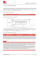
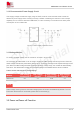
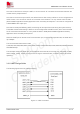
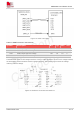
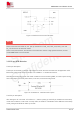
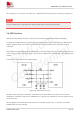
Table Of Contents
- 1.Introduction
- 2.Package Information
- 3.Interface Application
- 4.RF Specifications
- 5.Electrical Specifications
- 6.SMT Production Guide
- 7.Packaging
- 8.Appendix

SIM7075G User Manual V1.00
www.simcom.com 21 / 74
3. Interface Application
3.1 Power Supply
Pin 32, pin 33 and pin 52, pin 53 are VBAT power input.
On VBAT pads, when module works on CAT-M1 mode, the ripple current is up to 0.6A typically. For steady
voltage, the power supply capability must be up to 0.5A.
On VBAT pads, when module works on EDGE or GPRS mode, The ripple current is up to 2A typically. For
steady voltage, the power supply capability must be up to 2A. in order to avoid the voltage dropped down
more than 300mV, the load capacitor on VBAT pads must be up to 300uF.
The figure 5shows the VBAT voltage ripple wave at the maximum power transmit phase in EDGE/GPRS
emission mode.
Figure 5: Voltage drop in EDGE or GPRS mode
Table 6 describes the electrical characteristics of the VBAT pin and the current consumption of the module
in different modes.
Table 6: VBAT pins electronic characteristic
Symbol
Description
Min
Typ
Max
Unit
VBAT
Module power voltage
SIM7070G
3.3
3.8
4.3
V
IVBAT(peak)
Module power peak current in CAT-M1 and NB-IoT
emission mode.
-
0.5
-
A
IVBAT(avera
ge)
Module power average current in normal mode
Please refer to the chapter 5.4
IVBAT(sleep
)
Power supply current in sleep mode
IVBAT(powe
r-off)
Module power current in power off mode.
-
-
20
uA
IVBAT(PSM)
Module power current in PSM mode.
-
3.5
-
uA