
User's Manual
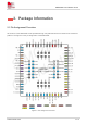
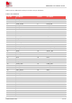
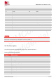
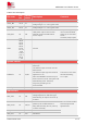
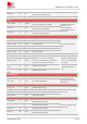
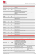
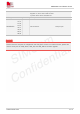
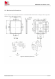
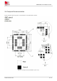
Table Of Contents
- 1.Introduction
- 2.Package Information
- 3.Interface Application
- 4.RF Specifications
- 5.Electrical Specifications
- 6.SMT Production Guide
- 7.Packaging
- 8.Appendix

SIM7075G User Manual V1.00
www.simcom.com 17 / 74
GPIO
NETLIGHT
52
DO
LED control output as network status
indication.
If unused, keep them
open.
STATUS
66
DO
Operating status output.
High level: Power on and firmware
ready
Low level: Power off
W_DISABLE#
18
DI
Airplane mode control
AP_READY
19
DI
Application processor sleep state
detection
GPIO31
16
IO
General purpose input/output, With
interrupt function
GPIO6
25
IO
General purpose input/output, Without
interrupt function.
GPIO7
26
IO
General purpose input/output, Without
interrupt function.
GPIO12
64
IO
General purpose input/output, With
interrupt function
GPIO13
65
IO
General purpose input/output, With
interrupt function
GPIO50
66
IO
General purpose input/output, With
interrupt function
GPIO57
83
IO
General purpose input/output, With
interrupt function
GPIO58
84
IO
General purpose input/output, With
interrupt function
GPIO52
85
IO
General purpose input/output, With
interrupt function
GPIO36
86
IO
General purpose input/output, With
interrupt function
GPIO40
87
IO
General purpose input/output, With
interrupt function
GPIO41
88
IO
General purpose input/output, With
interrupt function
GPIO20
93
IO
General purpose input/output, With
interrupt function
RF interface
ANT_GNSS
49
AI
GNSS antenna soldering pad
50Ω impedance
ANT_MAIN
60
AIO
MAIN antenna soldering pad
50Ω impedance
Other interface
BOOT_CFG
6
DI,PD
If it needs to enter into forced USB
download mode, it must be pulling up
this pin to VDD_EXT before press the
PWRKEY. If it needs to boot up
normally, please keep this pin open
Reserve a test points
for it. Keep it open.DO
NOT PULL UP DURING
NORMAL POWER UP!
ADC1
2
AI
Analog-digital converter input.
voltage range:0V~1.875V.
ADC0 and ADC1
cannot be used
Simultaneously, if
unused, keep them
open.
ADC0
24
AI
Analog-digital converter input.
voltage range:0V~1.875V.
PS_HOLD
94
DI
Power supply hold control input. This
signal’s main purpose is to tell the
C
max
=10 pF