
User's Manual
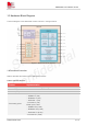
Table Of Contents
- 1.Introduction
- 2.Package Information
- 3.Interface Application
- 4.RF Specifications
- 5.Electrical Specifications
- 6.SMT Production Guide
- 7.Packaging
- 8.Appendix

SIM7075G User Manual V1.00
www.simcom.com 10 / 74
1.3 Hardware Block Diagram
The block diagram of the SIM7075G module is shown in the figure below.
Figure 1: SIM7075G block diagram
1.4Functional Overview
Table 2 describes the features of the SIM7075G modules.
Table 2: General features
Feature
Implementation
Power supply
SIM 7075G Power supply voltage 3.3V~4.3V. Default :3.8V
Power saving
Current in PSM mode: 9uA
Radio frequency bands
Please refer to the table 1
Transmitting power
GSM/GPRS power class:
-- GSM850: 4 (2W)
-- EGSM900: 4 (2W)
-- DCS1800: 1 (1W)
--PCS1900: 4 (1W)
EDGE power class:
-- GSM850: E2 (0.5W)
-- EGSM900: E2 (0.5W)
-- DCS1800: E1 (0.4W)
--PCS1900: E1 (0.4W)