
User's Manual

Smart Machine Smart Decision
SIM7600NA_user manual _V1.00 24 2020-1-7
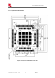
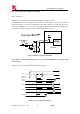
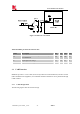
3.1.1 Power Supply Design Guide
Make sure that the voltage on the VBAT pins will never drop below 3.4V, even during a transmit
burst, when current consumption may rise up to 2A. If the voltage drops below 3.4V, the RF
performance may be affected.
Note: If the power supply for VBAT pins can support up to 2A, more than 300uF capacitors are
recommended .Otherwise users must use a total of 1000uF capacitors typically, in order to avoid
of the voltage drop more than 300mV.
Some multi-layer ceramic chip (MLCC) capacitors (0.1/1uF) with low ESR in high frequency band
can be used for EMC.
These capacitors should be put as close as possible to VBAT pads. Also, users should keep VBAT
trace on circuit board wider than 2 mm to minimize PCB trace impedance. The following figure
shows the recommended circuit.
Recommend Bead for vbat filter is BLM21PG300SN1D and MPZ2012S221A。
Figure 6: Power supply application circuit
In addition, in order to guard for over voltage protection, it is suggested to use TVS.
Note: user could only power pin 62, 63 or only power pin 38, 39, for these pins are connected
inside the MODULE.
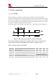
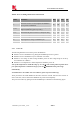
Table 7: Recommended TVS list
No. Manufacturer Part Number Power dissipation Package
1 JCET ESDBW5V0A1 5V DFN1006-2L
2 WAYON WS05DPF-B 5V DFN1006-2L
3 WILLSEMI ESD5611N 5V DFN1006-2L
4 WILLSEMI ESD56151W05 5V SOD-323
5* PRISEMI PESDHC2FD4V5BH 4.5V DFN1006-2L
6*
WAYON
WS4.5DPV 4.5V DFN1610-2L
Note: If user chooses TVS, please pay attention to Clamping Voltage in your datasheet . For
example when the surge input is 100V,the Clamping Voltage is less than 10V.
* If vbat is higher than 3.8V, do not choose 5 and 6.