
Specifications


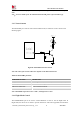
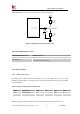
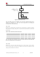
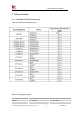

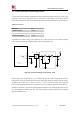
Table Of Contents

Smart Machine Smart Decision
SIM7600G_SIM7600G-H_Hardware Design _V1.01 41 2019-10-21
Figure29: SD reference circuit
Users should provide 2.85V to power eMMC card system and 1.8V to power the
SDIO_DATA/CMD/CLK signals. The source of 2.85V should be able to provide more than
500mA* which showed below as VCC_eMMC, as the source of 1.8V should be able to
provide more than 300mA* which showed below as VCCQ_1V8. ESD/EMI components
should be arranged close to the eMMC card. Refer to the following application circuit.
CMD
D3
SD_CMD
SD_DATA3
SD_DATA1
SD_DATA2
SD_DATA0
SD_CLK
D2
D1
D0
CLK
VCC
VCC
VCC
VCC
VCCQ
VCCQ
VCCQ
VCCQ
VDDIM
RST
D7
D6
D5
D4
DS
VCC_eMMC
VCCQ_1V8
VCCQ_1V8
eMMC
RESOUT_N
Module
Figure 30: eMMC reference circuit
*NOTE: For the current of VCC_eMMC and VCCQ_1V8, users should better refer to the
related datasheet of eMMC which is used. The listed current of 500mA and 300mA are just
for your reference.