
User's Manual
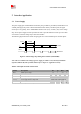
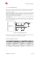
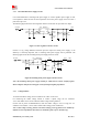
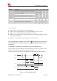
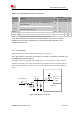
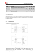
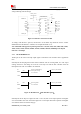
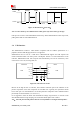
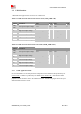
Table Of Contents
- RF Exposure Statement:
- General Notes
- Copyright
- Contents
- Table Index
- Figure Index
- Revision History
- 1Introduction
- 2Package Information
- 3Interface Application
- 3.1Power Supply
- Figure 5: VBAT voltage drop during burst emission
- 3.1.1Power Supply Design Guide
- Figure 6: Power supply application circuit
- Table 7: Recommended Zener diode list
- 3.1.2Recommended Power Supply Circuit
- Figure 7: Linear regulator reference circuit
- Figure 8: Switching mode power supply reference ci
- 3.1.3Voltage Monitor
- 3.2Power on/Power off/Reset Function
- 3.3UART Interface
- 3.4USB Interface
- 3.5USIM Interface
- 3.6PCM Interface
- 3.7SD Interface
- 3.8I2C Interface
- 3.9SDIO Interface
- 3.10SPI Interface
- 3.11Network status
- 3.12Flight Mode Control
- Switch
- 3.1Power Supply
- 4RF Specifications
- 5Electrical Specifications
- 6SMT Production Guide
- 7Packaging
- Appendix

SIM7600SA-H_User Manual_V1.00
2017-10-11
Smart Machine Smart Decision
3.2 Power on/Power off/Reset Function
3.2.1 Power on
SIM7600SA-H can be powered on by pulling the PWRKEY pin down to ground.
The PWRKEY pin has been pulled up with a diode to 1.8V internally, so it does not need to be
pulled up externally. It is strongly recommended to put a100nF capacitor, an ESD protection diode,
close to the PWRKEY pin as it would strongly enhance the ESD performance of PWRKEY pin.
Please refer to the following figure for the recommended reference circuit.
Power
On / off logic
The high voltage of PWRKEY is 0.8V
1.8V
Turn on / off
impulse
4.7K
PWRKEY
100
Ω
100nF
47K
MODULE
Figure 9: Reference power on/off circuit
Note: Module could be automatically power on by connecting PWRKEY pin to ground via 0R
resistor directly.
The power-on scenarios are illustrated in the following figure.
VBAT
PWRKEY
(Input)
STATUS
(Output)
T
on
T
on(status)
T
on(uart)
UART Port
Undefined
Active
USB Port T
on(usb)
Undefined
Active
Figure 10: Power on timing sequence