
Specifications
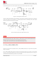

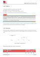
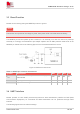
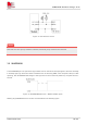
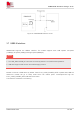

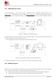
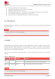
Table Of Contents
- 1 Introduction
- 2 Package Information
- 3 Interface Application
- 4 Antenna Interfaces
- 5 Electrical Specifications
- 6 Appearance
- 7 Packaging
- 8 Appendix

SIM6600-M2 Hardware Design V1.00
www.simcom.com
30
/
54
The traces should be as short as possible.
Keep SIM holder’s GND connect to main ground directly.
Shielding the SIM card signal by ground.
Recommended to place a 0.1~1uF capacitor on UIM-PWR line and keep close to the holder.
The rise/fall time of UIM-CLK should not be more than 40ns.
Add some TVS and the parasitic capacitance should not exceed 60pF.
3.9 I2S Interface*
Module provides an I2S interface for external codec, which comply with the requirements in the Phillips I2S
Bus Specifications.
“*”means the I2S function is under developing.
3.10DPR*
DPR (Dynamic Power Reduction) signal is used by SIM6600-M2 to assist in meeting regulatory SAR
(Specific Absorption Rate) requirements for RF exposure. The signal is provided by a host system
proximity sensor to the wireless device to provide an input trigger causing a reduction in the radio transmit
output power. The module have 2 DPR pins.
User can use AT command to active this function, if do not need this function, this pin can be keep
floating.
Table 17: DPR interface
Pin no Pin Name Pin status Function
25 PCI_DPR1#
Low Max transmitting power will be reduced
High Max transmitting power will not be reduced (default)
28 PCI_DPR2#
Floating Max transmitting power will not be reduced
“*” means the DRP function is under developing.
NOTE
NOTE