
Specifications
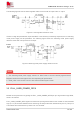

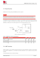
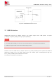

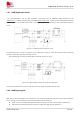
Table Of Contents
- 1 Introduction
- 2 Package Information
- 3 Interface Application
- 4 Antenna Interfaces
- 5 Electrical Specifications
- 6 Appearance
- 7 Packaging
- 8 Appendix

SIM6600-M2 Hardware Design V1.00
www.simcom.com
29
/
54
3.8.1 USIM Application Guide
It is recommended to use an ESD protection component such as ESDA6V1-5W6 produced by ST
(www.st.com ) or SMF12C produced by ON SEMI (www.onsemi.com ). Note that the USIM peripheral circuit
should be close to the USIM card socket. The following figure shows the 6-pin SIM card holder reference
circuit.
Figure 17: USIM interface reference circuit
The SIM Detect pin is used for detection of the UIM card hot plug in. User can select the 8-pin UIM card
holder to implement UIM card detection function.
The following figure shows the 8-pin SIM card holder reference circuit.
Figure 18: UIM interface reference circuit with UIM_DET
If the UIM card detection function is not used, user can keep the SIM Detect pin open.
3.8.2 USIM layout guide
SIM card circuit is susceptible, the interference may cause the SIM card failures or some other situations,
so it is strongly recommended to follow these guidelines while designing:
Make sure that the SIM card holder should be far away from the antenna while in PCB layout.
SIM traces should keep away from RF lines, VBAT and high-speed signal lines.