
Specifications
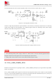


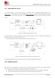
Table Of Contents
- 1 Introduction
- 2 Package Information
- 3 Interface Application
- 4 Antenna Interfaces
- 5 Electrical Specifications
- 6 Appearance
- 7 Packaging
- 8 Appendix

SIM6600-M2 Hardware Design V1.00
www.simcom.com
28
/
54
Figure 16: USB reference circuit
Because of the high bit rate on USB bus, more attention should be paid to the influence of the junction
capacitance of the ESD component on USB data lines.
Typically, for the USB2.0 signals (USB D- and USB D+), the capacitance should not be more than 3pF. It is
recommended to use an ESD protection component such as ESD9M5.0ST5G provided by On
Semiconductor (www.onsemi.com ).
3.8 UIM Interface
Module supports both 1.8V and 3.0V UIM Cards.
Table 13: UIM electronic characteristic in 1.8V mode (UIM-PWR=1.8V)
Symbol Parameter Min. Typ. Max. Unit
UIM-PWR LDO power output voltage 1.75 1.8 1.95 V
V
IH
High-level input voltage 0.65*UIM-PWR - UIM-PWR +0.3 V
V
IL
Low-level input voltage -0.3 0 0.35*UIM-PWR V
V
OH
High-level output voltage UIM-PWR -0.45 - UIM-PWR V
V
OL
Low-level output voltage 0 0 0.45 V
Table 14: UIM electronic characteristic 3.0V mode (UIM-PWR=2.85V)
Symbol Parameter Min. Typ. Max. Unit
UIM-PWR LDO power output voltage 2.75 2.85 3.05 V
V
IH
High-level input voltage 0.65*UIM-PWR - UIM-PWR +0.3 V
V
IL
Low-level input voltage -0.3 0 0.25*UIM-PWR V
V
OH
High-level output voltage UIM-PWR -0.45 - UIM-PWR V
V
OL
Low-level output voltage 0 0 0.45 V