
Specifications
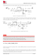

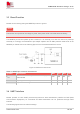
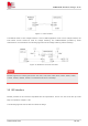
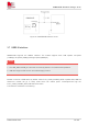

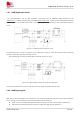
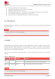
Table Of Contents
- 1 Introduction
- 2 Package Information
- 3 Interface Application
- 4 Antenna Interfaces
- 5 Electrical Specifications
- 6 Appearance
- 7 Packaging
- 8 Appendix

SIM6600-M2 Hardware Design V1.00
www.simcom.com
24
/
54
3.3 Reset Function
Module can be reset by pulling the RESET# pin down to ground.
This function is only used as an emergency reset, when power off AT command have lost efficacy.
The RESET# pin has been pulled up with a resistor to 1.8V internally, so it does not need to be pulled up
externally. It is strongly recommended to put a100pF capacitor and an ESD protection diode close to the
RESET# pin. Please refer to the following figure for the recommended reference circuit.
Figure 10: Reference reset circuit
Table 11: RESET pin electronic characteristic
Symbol Description Min. Typ. Max. Unit
T
reset
The active low level impulse time on RESET_N pin to
reset Module
100 150 500 ms
V
IH
Input high level voltage 1.2 1.8 2.1 V
V
IL
Input low level voltage -0.3 0 0.4 V
3.4 UART interface
Module provides a 2-wire UART (universal asynchronous serial transmission) interface as DCE (Data
Communication Equipment). AT commands and data transmission can be performed through UART
interface.
The following figures show the reference design.
NOTE