
Specifications
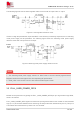

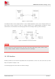
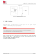

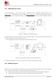
Table Of Contents
- 1 Introduction
- 2 Package Information
- 3 Interface Application
- 4 Antenna Interfaces
- 5 Electrical Specifications
- 6 Appearance
- 7 Packaging
- 8 Appendix

SIM6600-M2 Hardware Design V1.00
www.simcom.com
21
/
54
The following figure shows the linear regulator reference circuit with 5V input and 3.7V output.
Figure 5: Linear regulator reference circuit
If there is a high dropout between input and VBAT, or the efficiency is extremely important, then a switching
mode power supply will be preferable. The following figure shows the switching mode power supply
reference circuit with 12V input and 3.7V output.
Figure 6: Switching mode power supply reference circuit
1. The Switching Mode power supply solution for VBAT must be chosen carefully against Electro
Magnetic Interference and ripple current from depraving RF performance.
2. PWR_CTRL must connect to host in case that the module system crash.
3.2 FULL_CARD_POWER_OFF#
Module can be powered on by pulling the FULL_CARD_POWER_OFF# pin up to high level through GPIO,
which is 5V tolerant.
FULL_CARD_POWER_OFF# signal is an active low input signal and will turn the module on when asserted
high (≥1.7 V) and module will disconnect usb and go to sleep mode when asserted low (≤0.2 V). This pin is
3.3V tolerant and can be driven by either 1.8V or 3.3V GPIO .
NOTE