
Specifications
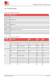
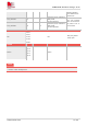
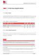
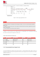
Table Of Contents
- 1 Introduction
- 2 Package Information
- 3 Interface Application
- 4 Antenna Interfaces
- 5 Electrical Specifications
- 6 Appearance
- 7 Packaging
- 8 Appendix

SIM6600-M2 Hardware Design V1.00
www.simcom.com
20
/
54
Interference.Recommend part of FB101 is BLM21PG300SN1D or MPZ2012S221A.
Figure 4: Power supply application circuit
1. The test condition: The voltage of power supply for VBAT is 3.7V, Ca is 100 µF tantalum capacitor
(ESR=0.7Ω).
2. PIN3,5,71,73 are the main return current path of module,these pins should be coppered by a ground
plane to main ground.
3. All other GND pins also need connect to ground.
In addition, in order to guard for over voltage protection, it is suggested to use a TVS diode to protect the
M.2 card.TVS diode should be placed near VBAT pins.
Table 8: Recommended TVS diode list
No. Manufacturer Part Number VRWM Package
1 JCET ESDBW5V0A1 5V DFN1006-2L
2 WAYON WS05DPF-B 5V DFN1006-2L
3 WILL ESD5611N 5V DFN1006-2L
4
WILL ESD56151W05 5V SOD-323
3.1.2 Recommended Power Supply Circuit
It is recommended that a switching mode power supply or a linear regulator power supply is used. It is
important to make sure that all the components used in the power supply circuit can resist the current which
could be more than 1A.
NOTE