
Specifications
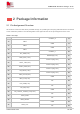
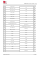
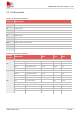
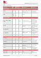
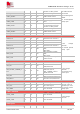
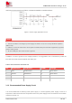
Table Of Contents
- 1 Introduction
- 2 Package Information
- 3 Interface Application
- 4 Antenna Interfaces
- 5 Electrical Specifications
- 6 Appearance
- 7 Packaging
- 8 Appendix

SIM6600-M2 Hardware Design V1.00
www.simcom.com
15
/
54
Table 6: Pin description
Pin name
Pin
No.
Electrical
Description
Description Comment
Power supply
VBAT
2,4,70,
72,74
PI
M,2 card power supply,
voltage range: 3.135 ~
4.4V, typical 3.7V.
User should
connect these
pins together.
GND
3,5,11,
27,33,
39,45,
51,57,
71,73
Ground
System Control
FULL_CARD_POWER_
OFF#
6 DI,PD
H: WWAN powers on.
L: WWAN go to sleep mode.
It’s internally
pulled to Low.
It’s 3.3V tolerant
but can be driven
by either 1.8V or
3.3V GPIO.
Reset# 67 P3 DI,PU
System reset control input,
active low.
RESET_N has
been pulled up to
1.8V via resistor
internally.
W_DISABLE1# 8 DI
WWAN RF Disable, active
low.
It’s 3.3V tolerant
but can be driven
by either 1.8V or
3.3V GPIO.
W_DISABLE2# 26
DI
GNSS disable, active
low.Reserved.
It’s 3.3V tolerant
but can be driven
by either 1.8V or
3.3V GPIO.
WoWWAN# 23 OD
Wake on the host.Active
low.
Configuration pins
CONFIG0 21
GND Connect to ground
SIM6600-M2
module is
configured as the
WWAN USB2.0
interface type.
CONFIG1 69 GND Connect to ground
CONFIG2 75 GND Connect to ground
CONFIG3 1 NC Not connected
USB2.0/USB3.0
USB_D+ 7 AIO
Positive line of the
differential, bi-directional
USB signal.
Main
communication
interface.
USB2.0 data rate
up to 480Mbps.
USB D- 9 AIO
Negative line of the
differential, bi-directional
USB signal.
UIM interface
UIM1_PWR 36
PO
Power supply for UIM1
card.
1.8V/3.0V
voltage
domain,all lines
UIM1_DATA 34 P4 DIO
UIM1 Card data I/O, which
no need reserve Pull up