
Specifications
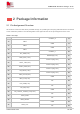
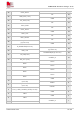
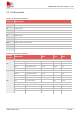
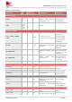
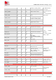
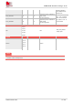
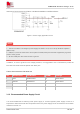
Table Of Contents
- 1 Introduction
- 2 Package Information
- 3 Interface Application
- 4 Antenna Interfaces
- 5 Electrical Specifications
- 6 Appearance
- 7 Packaging
- 8 Appendix

SIM6600-M2 Hardware Design V1.00
www.simcom.com
12
/
54
2 Package Information
2.1 Pin Assignment Overview
All functions of the M.2 card will be provided through 75 (including 8 notch pins) pads that will be connected
to the customers’ platform. The following table is the high-level view of the pin assignment of the card.
Table 3: Pin map
CONFIG_2 75
74 VBAT
GND 73
72 VBAT
GND 71
70 VBAT
CONFIG_1 69
68 I2C_SDA(1.8V)
RESET#(I)(1.8V) 67
66 UIM1_DET (1.8V)
ANTCTL3(O)(1.8V) 65
64 UART_TXD(1.8V)
ANTCTL2(O)(1.8V) 63
62 UART_RXD(1.8V)
ANTCTL1(O)(1.8V) 61
60 I2S_MCLK(1.8V)
ANTCTL0(O)(1.8V) 59
58 MIPI_DATA(1.8V)
GND 57
56 MIPI_CLK(1.8V)
NC 55
54 I2C_IRQ#(1.8V)
NC 53
52 I2S_WS(1.8V)
GND 51
50 I2S_TX/ANT_TUNER_CFG(1.8V)
NC 49
48 UIM2_PWR
NC 47
46 UIM2_RESET
GND 45
44 UIM2_CLK
NC 43