
Specifications
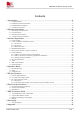
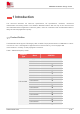
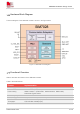
Table Of Contents
- 1Introduction
- 1.1Product Outline
- 1.2Hardware Interface Overview
- 1.3Hardware Block Diagram
- 1.4Functional Overview
- 2Package Information
- 2.1Pin Assignment Overview
- 2.2Pin Description
- 2.3Mechanical Information
- 2.4Footprint Recommendation
- 3Interface Application
- 3.1Power Supply
- 3.3WAKEUP Description
- 3.5UART Interface
- 3.6RI signal behaviors
- 3.7ADC
- 3.8SIM Card Interface
- 3.9Network Status
- 4Operation Mode
- 4.1Operating mode
- 4.2PSM
- 4.3PSM wake up
- 5RF Specifications
- 5.1LTE RF Specifications
- 5.2LTE Antenna Design Guide
- 5.3RF Layout Design Guide
- 6Electrical Specifications
- 6.1Normal Operating Conditions
- 6.2Current Consumption
- 6.3ESD Notes
- 7SMT Production Guide
- 7.1Top and Bottom View of SIM7028
- 7.2Typical SMT Reflow Profile
- 7.4Baking
- 8Packaging
- 8.1Tray packaging
- 9Appendix

SIM7028 Hardware Design V1.00
www.simcom.com 8 / 48
1 Introduction
This document describes the electronic specifications, RF specifications, interfaces, mechanical
characteristics and testing results of the SIMCom SIM7028 module. With the help of this document and
other SIM7028 software application notes/user guides, users can understand and use SIM7028 module to
design and develop applications quickly.
1.1 Product Outline
The SIM7028 module support LTE Category NB2, 2-HARQ. The physical dimension of SIM7028 is 17.6mm
×15.7mm×2.3 mm. It is designed for applications that need low latency, Low throughput data
communication in a variety of radio propagation conditions.
Table 1: SIM7028 frequency bands
Network
Type
Band
SIM7028
LTE-HD-FDD
Category
NB2
LTE-FDD B1
LTE-FDD B2
LTE-FDD B3
LTE-FDD B4
LTE-FDD B5
LTE-FDD B8
LTE-FDD B12
LTE-FDD B13
LTE-FDD B14
LTE-FDD B17
LTE-FDD B18
LTE-FDD B19
LTE-FDD B20
LTE-FDD B25
LTE-FDD B26
LTE-FDD B28
LTE-FDD B66
LTE-FDD B70
LTE-FDD B85