
Specifications
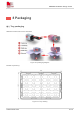
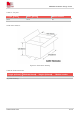
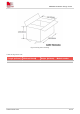


Table Of Contents
- 1Introduction
- 1.1Product Outline
- 1.2Hardware Interface Overview
- 1.3Hardware Block Diagram
- 1.4Functional Overview
- 2Package Information
- 2.1Pin Assignment Overview
- 2.2Pin Description
- 2.3Mechanical Information
- 2.4Footprint Recommendation
- 3Interface Application
- 3.1Power Supply
- 3.3WAKEUP Description
- 3.5UART Interface
- 3.6RI signal behaviors
- 3.7ADC
- 3.8SIM Card Interface
- 3.9Network Status
- 4Operation Mode
- 4.1Operating mode
- 4.2PSM
- 4.3PSM wake up
- 5RF Specifications
- 5.1LTE RF Specifications
- 5.2LTE Antenna Design Guide
- 5.3RF Layout Design Guide
- 6Electrical Specifications
- 6.1Normal Operating Conditions
- 6.2Current Consumption
- 6.3ESD Notes
- 7SMT Production Guide
- 7.1Top and Bottom View of SIM7028
- 7.2Typical SMT Reflow Profile
- 7.4Baking
- 8Packaging
- 8.1Tray packaging
- 9Appendix
OEM/Integrators Installation Manual
Important Notice to OEM integrators 1. This module is limited to OEM installation ONLY. 2. This module
is limited to installation in mobile or fixed applications, according to Part 2.1091(b). 3. The separate
approval is required for all other operating configurations, including portable configurations with respect
to Part 2.1093 and different antenna configurations 4. For FCC Part 15.31 (h) and (k): The host
manufacturer is responsible for additional testing to verify compliance as a composite system. When
testing the host device for compliance with Part 15 Subpart B, the host manufacturer is required to show
compliance with Part 15 Subpart B while the transmitter module(s) are installed and operating. The
modules should be transmitting and the evaluation should confirm that the module's intentional
emissions are compliant (i.e. fundamental and out of band emissions). The host manufacturer must
verify that there are no additional unintentional emissions other than what is permitted in Part 15 Subpart
B or emissions are complaint with the transmitter(s) rule(s). The Grantee will provide guidance to the
host manufacturer for Part 15 B requirements if needed.
Important Note
notice that any deviation(s) from the defined parameters of the antenna trace, as described by the
instructions, require that the host product manufacturer must notify to Simcom that they wish to change
the antenna trace design. In this case, a Class II permissive change application is required to be filed by
the USI, or the host manufacturer can take responsibility through the change in FCC ID (new application)
procedure followed by a Class II permissive change application
End Product Labeling
When the module is installed in the host device, the FCC ID label must be visible through a window on
the final device or it must be visible when an access panel, door or cover is easily re-moved. If not, a
second label must be placed on the outside of the final device that contains the following text: “Contains
FCC ID: 2AJYU-8EC0001” “The FCC ID can be used only when all FCC compliance requirements are
met.