
Specifications

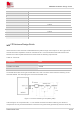
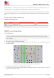
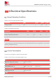
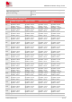

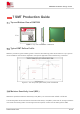
Table Of Contents
- 1Introduction
- 1.1Product Outline
- 1.2Hardware Interface Overview
- 1.3Hardware Block Diagram
- 1.4Functional Overview
- 2Package Information
- 2.1Pin Assignment Overview
- 2.2Pin Description
- 2.3Mechanical Information
- 2.4Footprint Recommendation
- 3Interface Application
- 3.1Power Supply
- 3.3WAKEUP Description
- 3.5UART Interface
- 3.6RI signal behaviors
- 3.7ADC
- 3.8SIM Card Interface
- 3.9Network Status
- 4Operation Mode
- 4.1Operating mode
- 4.2PSM
- 4.3PSM wake up
- 5RF Specifications
- 5.1LTE RF Specifications
- 5.2LTE Antenna Design Guide
- 5.3RF Layout Design Guide
- 6Electrical Specifications
- 6.1Normal Operating Conditions
- 6.2Current Consumption
- 6.3ESD Notes
- 7SMT Production Guide
- 7.1Top and Bottom View of SIM7028
- 7.2Typical SMT Reflow Profile
- 7.4Baking
- 8Packaging
- 8.1Tray packaging
- 9Appendix

SIM7028 Hardware Design V1.00
www.simcom.com 40 / 48
7 SMT Production Guide
7.1 Top and Bottom View of SIM7028
Figure 20: Top and bottom view of SIM7028
7.2 Typical SMT Reflow Profile
SIMCom provides a typical soldering profile. Therefore the soldering profile shown below is only a generic
recommendation and should be adjusted to the specific application and manufacturing constraints.
Figure 21: The ramp-soak-spike reflow profile of SIM7028
7.3 Moisture Sensitivity Level (MSL)
SIM7028 is qualified to Moisture Sensitivity Level (MSL) 3 in accordance with JEDEC J-STD-033.
The following table shows the features of Moisture Sensitivity Level (MSL). After seal off, storage conditions
must meet the following table. If the storage time was expired, module must be baking before SMT.