
Specifications

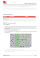
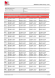

Table Of Contents
- 1Introduction
- 1.1Product Outline
- 1.2Hardware Interface Overview
- 1.3Hardware Block Diagram
- 1.4Functional Overview
- 2Package Information
- 2.1Pin Assignment Overview
- 2.2Pin Description
- 2.3Mechanical Information
- 2.4Footprint Recommendation
- 3Interface Application
- 3.1Power Supply
- 3.3WAKEUP Description
- 3.5UART Interface
- 3.6RI signal behaviors
- 3.7ADC
- 3.8SIM Card Interface
- 3.9Network Status
- 4Operation Mode
- 4.1Operating mode
- 4.2PSM
- 4.3PSM wake up
- 5RF Specifications
- 5.1LTE RF Specifications
- 5.2LTE Antenna Design Guide
- 5.3RF Layout Design Guide
- 6Electrical Specifications
- 6.1Normal Operating Conditions
- 6.2Current Consumption
- 6.3ESD Notes
- 7SMT Production Guide
- 7.1Top and Bottom View of SIM7028
- 7.2Typical SMT Reflow Profile
- 7.4Baking
- 8Packaging
- 8.1Tray packaging
- 9Appendix

SIM7028 Hardware Design V1.00
www.simcom.com 37 / 48
6 Electrical Specifications
6.1 Normal Operating Conditions
Table 21: Recommended operating ratings
Parameter
Min.
Typ.
Max.
Unit
Voltage at VBAT
2.2
-
4.3
V
Table 22: Operating temperature
Parameter
Min.
Typ.
Max.
Unit
Normal operating temperature
-30
25
80
℃
Extreme operating temperature
-40
25
85
℃
Storage temperature
-45
25
90
℃
The performance will be reduced slightly from the 3GPP specifications if the temperature in the extreme
operating temperature range.
6.2 Current Consumption
The current consumption is listed in the table below.
Table 23: VBAT current consumption(VBAT=3.3V)
I
MAX
Peak current
(Maximum transient current)
Data transmission at maximum output power
Typical: 500mA
Idle mode
LTE supply current
(AT$QCPMUCFG=1,1)
NB-IoT Idle mode Typical: 5mA
Power Saving Mode
PSM supply current
T3324=20S,T3412=600S,DRX=2.56S, PSM mode
Typical: 0.8uA
e-DRX
NOTE