
Specifications
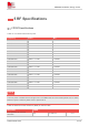

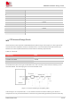
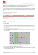
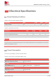
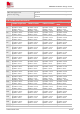

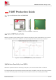
Table Of Contents
- 1Introduction
- 1.1Product Outline
- 1.2Hardware Interface Overview
- 1.3Hardware Block Diagram
- 1.4Functional Overview
- 2Package Information
- 2.1Pin Assignment Overview
- 2.2Pin Description
- 2.3Mechanical Information
- 2.4Footprint Recommendation
- 3Interface Application
- 3.1Power Supply
- 3.3WAKEUP Description
- 3.5UART Interface
- 3.6RI signal behaviors
- 3.7ADC
- 3.8SIM Card Interface
- 3.9Network Status
- 4Operation Mode
- 4.1Operating mode
- 4.2PSM
- 4.3PSM wake up
- 5RF Specifications
- 5.1LTE RF Specifications
- 5.2LTE Antenna Design Guide
- 5.3RF Layout Design Guide
- 6Electrical Specifications
- 6.1Normal Operating Conditions
- 6.2Current Consumption
- 6.3ESD Notes
- 7SMT Production Guide
- 7.1Top and Bottom View of SIM7028
- 7.2Typical SMT Reflow Profile
- 7.4Baking
- 8Packaging
- 8.1Tray packaging
- 9Appendix

SIM7028 Hardware Design V1.00
www.simcom.com 32 / 48
5 RF Specifications
5.1 LTE RF Specifications
Table 15: Conducted transmission power
Frequency
Power
Min.
LTE-FDD B1
23dBm +/-2.7dB
<-40dBm
LTE-FDD B2
23dBm +/-2.7dB
<-40dBm
LTE-FDD B3
23dBm +/-2.7dB
<-40dBm
LTE-FDD B4
23dBm +/-2.7dB
<-40dBm
LTE-FDD B5
23dBm +/-2.7dB
<-40dBm
LTE-FDD B8
23dBm +/-2.7dB
<-40dBm
LTE-FDD B12
23dBm +/-2.7dB
<-40dBm
LTE-FDD B13
23dBm +/-2.7dB
<-40dBm
LTE-FDD B14
23dBm +/-2.7dB
<-40dBm
LTE-FDD B17
23dBm +/-2.7dB
<-40dBm
LTE-FDD B18
23dBm +/-2.7dB
<-40dBm
LTE-FDD B19
23dBm +/-2.7dB
<-40dBm
LTE-FDD B20
23dBm +/-2.7dB
<-40dBm
LTE-FDD B25
23dBm +/-2.7dB
<-40dBm
LTE-FDD B26
23dBm +/-2.7dB
<-40dBm
LTE-FDD B28
23dBm +/-2.7dB
<-40dBm
LTE-FDD B66
23dBm +/-2.7dB
<-40dBm
LTE-FDD B70
23dBm +/-2.7dB
<-40dBm
LTE-FDD B85
23dBm +/-2.7dB
<-40dBm
The max power is tested result for single-tone in CAT-NB2. Multi-tone test results please refer to 3GPP,
Maximum power reduction please refer to part 6.2.3F.3.
Table 16: Maximum Power Reduction (MPR) for UE CAT NB2
Modulation
QPSK
Tone positions for 3 Tones
allocation
0-2
3-5 and 6-8
9-11
NOTE