
Specifications
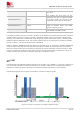
Table Of Contents
- 1Introduction
- 1.1Product Outline
- 1.2Hardware Interface Overview
- 1.3Hardware Block Diagram
- 1.4Functional Overview
- 2Package Information
- 2.1Pin Assignment Overview
- 2.2Pin Description
- 2.3Mechanical Information
- 2.4Footprint Recommendation
- 3Interface Application
- 3.1Power Supply
- 3.3WAKEUP Description
- 3.5UART Interface
- 3.6RI signal behaviors
- 3.7ADC
- 3.8SIM Card Interface
- 3.9Network Status
- 4Operation Mode
- 4.1Operating mode
- 4.2PSM
- 4.3PSM wake up
- 5RF Specifications
- 5.1LTE RF Specifications
- 5.2LTE Antenna Design Guide
- 5.3RF Layout Design Guide
- 6Electrical Specifications
- 6.1Normal Operating Conditions
- 6.2Current Consumption
- 6.3ESD Notes
- 7SMT Production Guide
- 7.1Top and Bottom View of SIM7028
- 7.2Typical SMT Reflow Profile
- 7.4Baking
- 8Packaging
- 8.1Tray packaging
- 9Appendix

SIM7028 Hardware Design V1.00
www.simcom.com 29 / 48
4 Operation Mode
4.1 Operating mode
SIM7028 module has modes which are listed below:
Table 13: Module operating mode
Mode function
Description
Normal
operating
mode
Active
Power saving mode is not active, the system will stay in
loop-waiting status, even has no tasks, high power
consumption. All the function work properly for data
transmitting and receiving.
Idle
The core clock will be shut down when the system has no
tasks, any interrupt could wake up the system and restart the
core clock. IDLE mode only receive the paging message,
which means monitor the network paging, if the data detected,
the module will switch to ACTIVE mode from IDLE mode.
Sleep
The module will shut down all the peripherals and part of
registers based on the IDLE mode, the interrupt of the
peripherals cannot wake up the system. The paging message
cannot be received in SLEEP mode. When the module needs
to receive the paging message, it will switch to IDLE mode to
receive the network paging message, then switch to SLEEP
mode.
PSM
CPU will be shut down, only RTC function works; the network is
disconnect and the module cannot receive the download data;
the module can exist PSM mode by setting the timer of RTC
and switch to ACTIVE mode.
The module can be configured to different sleep mode, which the system shuts down the different number
of the internal power supply, to has different power consumption. The sleep mode can be set by AT
command “AT+ECPMUCFG” and “AT+ECPMUCFG=1,4” as default.
The detailed information is listed below:
Table 14: Sleep mode
AT command
Setting mode
Description
AT+ECPMUCFG=0
Active
Power saving mode is not active, the
system will stay in loop-waiting status,
even has no tasks, high power
consumption.
AT+ECPMUCFG=1,1
Idle
The core clock will be shut down when
the system has no tasks, any interrupt