
Specifications
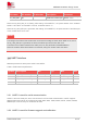
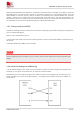
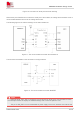
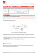
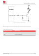
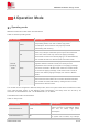
Table Of Contents
- 1Introduction
- 1.1Product Outline
- 1.2Hardware Interface Overview
- 1.3Hardware Block Diagram
- 1.4Functional Overview
- 2Package Information
- 2.1Pin Assignment Overview
- 2.2Pin Description
- 2.3Mechanical Information
- 2.4Footprint Recommendation
- 3Interface Application
- 3.1Power Supply
- 3.3WAKEUP Description
- 3.5UART Interface
- 3.6RI signal behaviors
- 3.7ADC
- 3.8SIM Card Interface
- 3.9Network Status
- 4Operation Mode
- 4.1Operating mode
- 4.2PSM
- 4.3PSM wake up
- 5RF Specifications
- 5.1LTE RF Specifications
- 5.2LTE Antenna Design Guide
- 5.3RF Layout Design Guide
- 6Electrical Specifications
- 6.1Normal Operating Conditions
- 6.2Current Consumption
- 6.3ESD Notes
- 7SMT Production Guide
- 7.1Top and Bottom View of SIM7028
- 7.2Typical SMT Reflow Profile
- 7.4Baking
- 8Packaging
- 8.1Tray packaging
- 9Appendix

SIM7028 Hardware Design V1.00
www.simcom.com 26 / 48
Pin name
Pin number
I/O
Description
Comment
SIM_DATA
15
I/O
SIM data input/output
SIM_RST
16
DO
SIM reset
SIM_CLK
17
DO
SIM clock
SIM_VDD
18
PO
Voltage supply for SIM card.
Support 1.8V or 3V SIM card
depends on SIM card type
3.0 V < VBAT ≤ 4.5 V, 1.8/3.0 V SIM card is supported;
2.2 V ≤ VBAT ≤ 3 V, only 1.8 V SIM card is supported.
The following figure is the reference circuit for SIM card. The component of circuit should be placed as
close as possible to the SIM card holder.
Figure 14: Reference circuit of SIM card interface
SIM card signal could be interference by some high frequency signal, it is strongly recommended to
follow these guidelines while designing:
Add some TVS which parasitic capacitance should not exceed 50pF
SIM card holder should be far away from GSM antenna
SIM traces should keep away from RF lines, VBAT and high-speed signal lines, the traces should be as
short as possible
Keep SIM card holder’s GND connect to main ground directly
Shielding the SIM_CLK to prevent the interference to other signals
3.9 Network Status
NETLIGHT pin to indicate the current network status, which is used to control Network Status LED, its
reference circuit is shown in the following figure.
※
Note