
Specifications
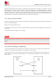
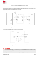
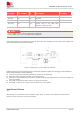
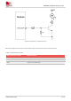
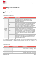
Table Of Contents
- 1Introduction
- 1.1Product Outline
- 1.2Hardware Interface Overview
- 1.3Hardware Block Diagram
- 1.4Functional Overview
- 2Package Information
- 2.1Pin Assignment Overview
- 2.2Pin Description
- 2.3Mechanical Information
- 2.4Footprint Recommendation
- 3Interface Application
- 3.1Power Supply
- 3.3WAKEUP Description
- 3.5UART Interface
- 3.6RI signal behaviors
- 3.7ADC
- 3.8SIM Card Interface
- 3.9Network Status
- 4Operation Mode
- 4.1Operating mode
- 4.2PSM
- 4.3PSM wake up
- 5RF Specifications
- 5.1LTE RF Specifications
- 5.2LTE Antenna Design Guide
- 5.3RF Layout Design Guide
- 6Electrical Specifications
- 6.1Normal Operating Conditions
- 6.2Current Consumption
- 6.3ESD Notes
- 7SMT Production Guide
- 7.1Top and Bottom View of SIM7028
- 7.2Typical SMT Reflow Profile
- 7.4Baking
- 8Packaging
- 8.1Tray packaging
- 9Appendix

SIM7028 Hardware Design V1.00
www.simcom.com 22 / 48
Pin name
Pin number
I/O direction
Description
Comment
IO_1833_SEL
20
I
GPIO level control input
When floating, the pin
level is 1.1V
When the IO_1833_SEL pin is floating, after setting "AT+VIOSET=1", the power domain of the module's
GPIO is 1.8V. When "AT+VIOSET" is not set, its default value is "1".
When the IO_1833_SEL pin is grounded, after setting "AT+VIOSET=3", the power domain of the GPIO port
of the module will be set to 3.3V.
The voltage of the GPIO of the module will not exceed the voltage of VBAT. When VBAT<3.3V, even if
the IO_1833_SEL pin is grounded, the level of the GPIO port will be lower than 3.3V.
The GPIO of the module includes three UART ports, RI, SPI, NETLIGHT, SWDIO/SWDCLK.
When the module's GPIO level selection is switched, VDD_EXT will also follow the switch.
3.5 UART Interface
SIM7028 provides two serial ports: UART1 and UART0.
Table 9: UART electrical parameters
Symbol
Description
Min.
Typ.
Max.
Unit
VIH
Input high level voltage
0.7 x VDD_EXT
VDD_EXT
VDD_EXT
V
VIL
Input low level voltage
-0.3
0
0.2 x VDD_EXT
V
VOH
Output high level voltage
0.7 x VDD_EXT
VDD_EXT
VDD_EXT
V
VOL
Output low level voltage
0
0
0.45
V
3.5.1 UART1 is used for serial communication
UART1 is the main serial port, which can be used for AT command communication. UART1 supports
adaptive baud rate and can be configured as 2400, 4800, 9600, 19200, 38400, 57600, 115200, 230400,
460800 bps. It can be set by AT command "AT+IPR".
3.5.2 UART1 is used for firmware upgrade and calibration
NOTE