
Specifications
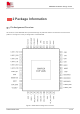
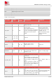
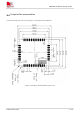
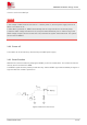
Table Of Contents
- 1Introduction
- 1.1Product Outline
- 1.2Hardware Interface Overview
- 1.3Hardware Block Diagram
- 1.4Functional Overview
- 2Package Information
- 2.1Pin Assignment Overview
- 2.2Pin Description
- 2.3Mechanical Information
- 2.4Footprint Recommendation
- 3Interface Application
- 3.1Power Supply
- 3.3WAKEUP Description
- 3.5UART Interface
- 3.6RI signal behaviors
- 3.7ADC
- 3.8SIM Card Interface
- 3.9Network Status
- 4Operation Mode
- 4.1Operating mode
- 4.2PSM
- 4.3PSM wake up
- 5RF Specifications
- 5.1LTE RF Specifications
- 5.2LTE Antenna Design Guide
- 5.3RF Layout Design Guide
- 6Electrical Specifications
- 6.1Normal Operating Conditions
- 6.2Current Consumption
- 6.3ESD Notes
- 7SMT Production Guide
- 7.1Top and Bottom View of SIM7028
- 7.2Typical SMT Reflow Profile
- 7.4Baking
- 8Packaging
- 8.1Tray packaging
- 9Appendix

SIM7028 Hardware Design V1.00
www.simcom.com 18 / 48
3 Interface Application
3.1 Power Supply
Pin 34 and pin 35 are VBAT power input.
The power supply for SIM7028 must be able to provide sufficient current up to more than 500mA in order to
satisfy the power supply current for maximum consumption.
The module can use an LDO with a low quiescent current output capability of 1 A as the power supply, or it
can be powered by a battery. When the module is working in the digital transmission mode, it must be
ensured that the power drop does not fall below the minimum working voltage of the module 2.2 V,
otherwise the module will be abnormal.
At the VBAT pin of the module, you can refer to the following devices, where CA is a low ESR 100
µ
F
tantalum capacitor. In addition, to prevent surges and static electricity, it is recommended to connect TVS in
parallel with the VBAT pin of the module. If you choose a Zener tube, please pay special attention to the
static power consumption of the Zener tube. During PCB layout, the capacitor and TVS should be as close
as possible to the VBAT pin of the module.
Figure 5: Power supply application circuit
3.2 Power on/Power off/Reset Function
3.2.1 Power on
The module is automatically turned on after power on, without a power button. Under the condition that the
RESET pin is not pulled low by the outside, the module will automatically power on after supplying a voltage