
Specifications
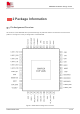
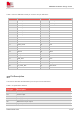
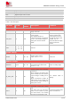
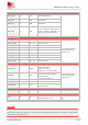
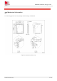
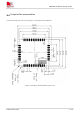
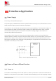
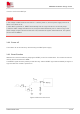
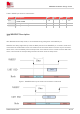
Table Of Contents
- 1Introduction
- 1.1Product Outline
- 1.2Hardware Interface Overview
- 1.3Hardware Block Diagram
- 1.4Functional Overview
- 2Package Information
- 2.1Pin Assignment Overview
- 2.2Pin Description
- 2.3Mechanical Information
- 2.4Footprint Recommendation
- 3Interface Application
- 3.1Power Supply
- 3.3WAKEUP Description
- 3.5UART Interface
- 3.6RI signal behaviors
- 3.7ADC
- 3.8SIM Card Interface
- 3.9Network Status
- 4Operation Mode
- 4.1Operating mode
- 4.2PSM
- 4.3PSM wake up
- 5RF Specifications
- 5.1LTE RF Specifications
- 5.2LTE Antenna Design Guide
- 5.3RF Layout Design Guide
- 6Electrical Specifications
- 6.1Normal Operating Conditions
- 6.2Current Consumption
- 6.3ESD Notes
- 7SMT Production Guide
- 7.1Top and Bottom View of SIM7028
- 7.2Typical SMT Reflow Profile
- 7.4Baking
- 8Packaging
- 8.1Tray packaging
- 9Appendix

SIM7028 Hardware Design V1.00
www.simcom.com 14 / 48
DO
Digital output
DOH
Digital output with high level
DOL
Digital output with low level
PU
Pull up
PD
Pull down
Table 5: Pin description
Pin name
Pin No.
Default
status
Description
Comment
Power supply
VBAT
34、35
PI
Power supply, voltage
range: 2.2-4.3V.
VDD_EXT
40
PO
Power output.
The voltage domain is
1.8V/3.3V optional. The default
is 1.8 V. The output voltage of
VDD_EXT will not exceed
VBAT.
There is no voltage
output in PSM mode.
It can supply power to
the pull-up circuit of the
module; it is not
recommended to supply
power to external
circuits.
GND
8、13、19、
21、27、30、
31、33、36、
37
Ground
System Control
RESET
28
DI,PU
System reset control
input, Vnorm = 1.3 V
Active low.
WAKEUP Control
WAKEUP
12,39
DI,PU
External interrupt pin; wake up
the module from PSM mode.
Vnorm = 1.3 V
Active on falling edge.
GPIO level selection
IO_1833_SEL
20
DI
Module GPIO level selection
control pin.
When floating: all GPIO levels
of the module are 1.8V and the
output voltage of VDD_EXT is
1.8V.
When connected to GND: all
GPIO levels of the module are
3.3V and the output voltage of
VDD_EXT is 3.3V.
The default state is
floating.
BOOT download control
BOOT
10
DI
Download control pin, active
low.
Pull down this pin and then
power on the module or press
the reset button, the module
will enter the download mode.
It cannot be pulled down
before normal boot.