
Specifications
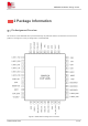
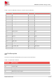
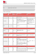
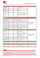
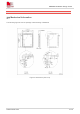
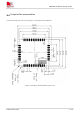
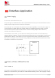
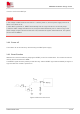
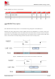
Table Of Contents
- 1Introduction
- 1.1Product Outline
- 1.2Hardware Interface Overview
- 1.3Hardware Block Diagram
- 1.4Functional Overview
- 2Package Information
- 2.1Pin Assignment Overview
- 2.2Pin Description
- 2.3Mechanical Information
- 2.4Footprint Recommendation
- 3Interface Application
- 3.1Power Supply
- 3.3WAKEUP Description
- 3.5UART Interface
- 3.6RI signal behaviors
- 3.7ADC
- 3.8SIM Card Interface
- 3.9Network Status
- 4Operation Mode
- 4.1Operating mode
- 4.2PSM
- 4.3PSM wake up
- 5RF Specifications
- 5.1LTE RF Specifications
- 5.2LTE Antenna Design Guide
- 5.3RF Layout Design Guide
- 6Electrical Specifications
- 6.1Normal Operating Conditions
- 6.2Current Consumption
- 6.3ESD Notes
- 7SMT Production Guide
- 7.1Top and Bottom View of SIM7028
- 7.2Typical SMT Reflow Profile
- 7.4Baking
- 8Packaging
- 8.1Tray packaging
- 9Appendix

SIM7028 Hardware Design V1.00
www.simcom.com 11 / 48
SIM interface
Support identity card: 1.8V/3V.
UART1 interface
A full modem serial port by default
Can be used as the AT commands
Can be used for firmware upgrade and RF calibration
Baud rate: default:115200bps
UART0
Software debugging and debugging log output. The default baud rate is
3Mbps.
Firmware upgrade
Firmware upgrade over UART1 interface
Physical characteristics
Size: 17.6mm×15.7mm×2.3 mm
Weight: 1.3g±0.2g
Temperature range
operation temperature: -40°C to +85°C
Storage temperature: -45°C to +90°C
When VBAT is lower than 3V, the radio frequency can work but the performance of some indicators
may not meet the 3GPP standard.
NOTE