
Users Manual Part 2


SIM7022-EVB User Guide V1.00
www.simcom.com
24
/
33
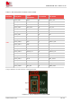
Table 12: The pin description of J106 on EVB
Position
Test point
Signal name
Description
J106
J106_PIN1
5V
EVB 5V power supply test point
J106_PIN2
GND
GND
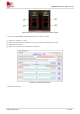
The pin definition of J107 is shown in the figure below.
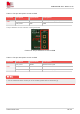
Feature 18: The pin definition of J107 on EVB
Table 13: The pin description of J107 on EVB
Position
Test point
Signal name
Description
J107
J107_PIN1
RESET
Module reset signal
J107_PIN2
GND
GND
J107_PIN3
WAKEUP
Module wake-up signal
1. For the related functions of each pin of the module, please refer to document [1].
※ Note