
User's Manual

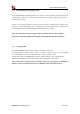


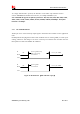


Table Of Contents
- Contents
- Table Index
- Revision History
- 1 Introduction
- 2 Package Information
- 3 Interface Application
- 4 RF Specifications
- 5 Electrical Specifications
- 6 SMT Production Guide
- 7 Packaging
- 空白页面

Smart Machine Smart Decision
SIM7600E-H_User Manual_V1.00 2017-10-11
3.5 USIM Interface
SIM7600E-H supports both 1.8V and 3.0V USIM Cards.
Table 11: USIM electronic characteristic in 1.8V mode (USIM_VDD=1.8V)
Symbol Parameter
Min. Typ. Max. Unit
USIM_
VDD
LDO power output voltage
1.75 1.8 1.95 V
V
IH
High-level input voltage
0.65*USIM_VDD - USIM_VDD +0.3 V
V
IL
Low-level input voltage
-0.3 0 0.35*USIM_VDD V
V
OH
High-level output voltage
USIM_VDD -0.45 - USIM_VDD V
V
OL
Low-level output voltage
0 0 0.45 V
Table 12: USIM electronic characteristic 3.0V mode (USIM_VDD=2.95V)
Symbol Parameter
Min. Typ. Max. Unit
USIM_
VDD
LDO power output voltage
2.75 2.95 3.05 V
V
IH
High-level input voltage
0.65*USIM_VDD - USIM_VDD +0.3 V
V
IL
Low-level input voltage
-0.3 0 0.25*USIM_VDD V
V
OH
High-level output voltage
USIM_VDD -0.45 - USIM_VDD V
V
OL
Low-level output voltage
0 0 0.45 V
3.5.1 USIM Application Guide
It is
re
commended to use an ESD protection component such as ESDA6V1W5 produced by ST
(www.st.com ) or SMF15C produced by ON SEMI (www.onsemi.com ). Note that the USIM
peripheral circuit should be close to the USIM card socket.
Note: USIM_DATA has been pulled up with a 1
00KΩ resistor to USIM_VDD in module. A
100nF capacitor on USIM_VDD is used to reduce interference. For more details of AT
commands about USIM, please refer to document [1].USIM_CLK is very important signal, the
rise time and fall time of USIM_CLK should be less than 40ns, otherwise the USIM card might
not be initialized correctly.