
User's Manual

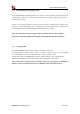


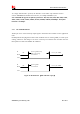


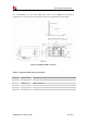
Table Of Contents
- Contents
- Table Index
- Revision History
- 1 Introduction
- 2 Package Information
- 3 Interface Application
- 4 RF Specifications
- 5 Electrical Specifications
- 6 SMT Production Guide
- 7 Packaging
- 空白页面

Smart Machine Smart Decision
SIM7600E-H_User Manual_V1.00 2017-10-11
3.1.1 Power Supply Design Guide
Make sure that the voltage on the VBAT pins will never dro
p
below 3.4V, even during a transmit
burst, when current consumption may rise up to 2A. If the voltage drops below 3.4V, the RF
performance may be affected.
Note: If the power supply for VBAT pins can support up to 2A, using a total of more than 300uF
capacitors is recommended, or else users must using a total of 1000uF capacitors typically, in
order to avoid the voltage drop is more than 300mV.
Some multi-layer ceramic chip (MLCC) capacitors (0.1/1uF) with low ESR in high frequency band
can be used for EMC.
These capacitors should be put as close as possible to VBAT pads. Also, users should keep VBAT
trace on circuit board wider than 2 mm to minimize PCB trace impedance.
In addition, in order to guard for over voltage protection, it is suggested to use a zener diode
with 5.1V reverse zener voltage and
more than 500mW power dissipation.
Table 7: Recommended Zener diode list
No. Manufacturer Part Number Power dissipation Package
1 On semi MMSZ5231BT1G 500mW SOD123
2 Prisemi PZ3D4V2H 500mW SOD323
3 Vishay MMSZ4689-V 500mW SOD123
4 Crownpo CDZ55C5V1SM 500mW 0805