
User's Manual
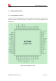


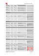


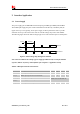
Table Of Contents
- Contents
- Table Index
- Revision History
- 1 Introduction
- 2 Package Information
- 3 Interface Application
- 4 RF Specifications
- 5 Electrical Specifications
- 6 SMT Production Guide
- 7 Packaging
- 空白页面

Smart Machine Smart Decision
SIM7600E-H_User Manual_V1.00 2017-10-11
3 Interface Application
3.1 Power Supply
The power supply pins of SIM7600E-H include 4 pins (pin 62&63, pin 38&39) named VBAT.
The 4 VBAT pads supply the power to RF and baseband circuits directly. On VBAT pads, the
ripple current up to 2A typically, So the power supply for these pads must be able to provide
sufficient current up to more than 2A in order to avoid the voltage drop is more than 300mV.
The following figure shows the VBAT voltage ripple wave at the maximum power transmit phase.
577us 4.615ms
Burst:2A
I
VBAT
VBAT
Max:300mV
Figure 5: VBAT voltage drop during burst emission
Note: The test condition: The voltage of power supply for VBAT is 3.8V, Cd=100 µF tantalum
capacitor (ESR=0.7Ω) and Cf=100nF (Please refer to Figure 6—Application circuit).
Table 6: VBAT pins electronic characteristic
Symbol Description Min. Typ. Max. Unit
VBAT
Module power voltage
3.4
3.8
4.2
V
I
VBAT(peak)
Module power peak current in normal mode.
-
2
-
A
I
VBAT(average)
Module power average current in normal mode
Please refer to the table 34
I
VBAT(sleep)
Power supply current in sleep mode
I
VBAT(power-off)
Module power current in power off mode. - - 20 uA