SIM7600E-H _User Manual_V1.
Smart Machine Smart Decision Document Title SIM7600E-H_User Manual Version 1.00 Date 2017-10-11 Status Released Document Control ID SIM7600E-H_User Manual_V1.00 RF Exposure Statement: For the product,under normal use condition is at least 20cm away from the b ody of the user,the user must keeping at least 20cm distance to the product. General Notes There are no restrictions of use SIM7500E-H module.
Smart Machine Smart Decision Contents Contents ............................................................................................................................................. 3 Table Index ........................................................................................................................................ 5 Revision History ................................................................................................................................ 7 1 Introduction .....
Smart Machine Smart Decision 3.13.3 LDO .......................................................................................................................... 38 4 RF Specifications ...................................................................................................................... 39 4.1 LTE RF Specifications ....................................................................................................... .39 4.2 LTE Antenna Design Guide......................................
Smart Machine Smart Decision Table Index Table 1: SIM7600E-H frequency bands ..............................................................................................................8 Table 2: General features ................................................................................................................................... 10 Table 3: Pin definition ........................................................................................................................................
Smart Machine Smart Decision Table 43: Safety Caution .................................................................................................................................... 57 SIM7600E-H_User Manual_V1.
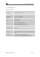
Smart Machine Smart Decision Revision History Data Version Description of change Author 2017-10-11 1.00 Original Ma Honggang Gao Fan SIM7600E-H_User Manual_V1.
Smart Machine Smart Decision 1 Introduction This document describes the electronic specifications, RF specifications, interfaces, mechanical characteristics and testing results of the SIMCom SIM7600E-H module. With the help of this document and other software application notes/user guides, users can understand and use module to design and develop applications quickly. 1.1 Product Outline Aimed at the Europe market, the SIM7600E-H module support FDD-LTE.
Smart Machine Smart Decision 1.2 Hardware Interface Overview The interfaces are described in detail in the next chapters include: ● Power Supply ● USB Interface ● UART Interface ● MMC/SD Interface ● SDIO Interface ● USIM Interface ● GPIO ● ADC ● LDO Power Output ● Current Sink Source ● PCM Interface ● SPI Interface ● I2C Interface SIM7600E-H_User Manual_V1.
Smart Machine Smart Decision 1.3 Functional Overview Table 2: General features Feature Implementation Power supply Single supply voltage 3.4~4.2V Power saving Current in sleep mode : <5mA Radio frequency bands Please refer to the table 1 Data Transmission Throughput LTE CAT 4 :150 Mbps (DL) LTE CAT 4 :50 Mbps (UL) Antenna LTE main antenna. LTE auxiliary antenna SMS MT, MO, CB, Text and PDU mode SMS storage: USIM card or ME(default) Transmission of SMS alternatively over CS or PS.
Smart Machine Smart Decision Can be used as the AT commands or data stream channel Support RTS/CTS hardware handshake Multiplex ability according to GSM 07.10 Multiplexer Protocol MMC/SD Support MMC and SD cards with 2.95 V on SD port SDIO Support SDIO with 1.8 V only on SDIO port USB USB 2.0 high speed interface Firmware upgrade Firmware upgrade over USB interface Physical characteristics Size:30*30*2.9m Weight:5.
Smart Machine Smart Decision 2 Package Information 2.1 Pin Assignment Overview All functions of the SIM7600E-H will be provided through 87 pads that will be connected to the customers’ platform. The following Figure is a high-level view of the pin assignment of the SIM7600E-H. Figure 2: Pin assignment overview SIM7600E-H_User Manual_V1.
Smart Machine Smart Decision Table 3: Pin definition Pin No. Pin name Pin No.
Smart Machine Smart Decision 69 RI 70 DCD 71 TXD 72 DTR 73 PCM_OUT 74 PCM_IN 75 PCM_SYNC 76 PCM_CLK 77 GND 78 GND 79 GNSS_ANT 80 GND 81 GND 82 MAIN_ANT 83 COEX1* 84 COEX2 85 BOOT_CFG0* 86 COEX3* 87 GPIO77 NOTE: Before the normal power up, GPIO43,COEX1, COEX3 and BOOT_CFG0 cannot be pulled up. 2.
Smart Machine Smart Decision VDD_1V8 15 GND 1,2,5, 10,14,37 ,40,41,4 3,57,58, 60,61,64 ,65,77,7 8,80,81 PO 1.8V SMPS output with Max 50mA current output for external circuit, such as level shift circuit. If unused, keep it open. Ground System Control DI,PU System power on/off control input, active low. The high voltage is 0.8V; 4 DI, PU System reset control input, active low. RESET has been pulled up to 1.8V via 40Kohm resistor internally.
Smart Machine Smart Decision USB_VBUS 11 DI,PD Valid USB detection input with 3.0~5.25V detection voltage USB_DN 12 I/O Negative line of the differential, bi-directional USB signal. USB_DP 13 I/O USB_ID 16 DI Positive line of the differential, bi-directional USB signal.
Smart Machine Smart Decision GPIO41 52 IO High level: Power on and firmware ready Low level: Power off GPIO GPIO43 50 IO GPIO GPIO3 33 IO GPIO GPIO6 34 IO GPIO Default: GPIO Optional: SD card detecting input. H: SD card is removed L: SD card is inserted Default: GPIO Optional: USIM card detecting input.
Smart Machine Smart Decision 2.3 Mechanical Information The following figure shows the package outline drawing of SIM7600E-H. Figure 3: Dimensions (Unit: mm) SIM7600E-H_User Manual_V1.
Smart Machine Smart Decision 2.4 Footprint Recommendation Figure 4: Footprint recommendation (Unit: mm) SIM7600E-H_User Manual_V1.
Smart Machine Smart Decision 3 Interface Application 3.1 Power Supply The power supply pins of SIM7600E-H include 4 pins (pin 62&63, pin 38&39) named VBAT. The 4 VBAT pads supply the power to RF and baseband circuits directly. On VBAT pads, the ripple current up to 2A typically, So the power supply for these pads must be able to provide sufficient current up to more than 2A in order to avoid the voltage drop is more than 300mV.
Smart Machine Smart Decision 3.1.1 Power Supply Design Guide Make sure that the voltage on the VBAT pins will never drop below 3.4V, even during a transmit burst, when current consumption may rise up to 2A. If the voltage drops below 3.4V, the RF performance may be affected.
Smart Machine Smart Decision 3.1.2 Recommended Power Supply Circuit It is recommended that a switching mode power supply or a linear regulator power supply is used. It is important to make sure that all the components used in the power supply circuit can resist a peak current up to 2A. If there is a big voltage difference between input and output for VBAT power supply, or the efficiency is extremely important, then a switching mode power supply will be preferable.
Smart Machine Smart Decision 3.2 3.2.1 Power on/Power off/Reset Function Power on SIM7600E-H can be powered on by pulling the PWRKEY pin down to ground. The PWRKEY pin has been pulled up with a diode to 1.8V internally, so it does not need to be pulled up externally. It is strongly recommended to put a100nF capacitor, an ESD protection diode, close to the PWRKEY pin as it would strongly enhance the ESD performance of PWRKEY pin.
Smart Machine Smart Decision Table 8: Power on timing and electronic characteristic Symbol Parameter Min. Typ. Max.
Smart Machine Smart Decision Table 9: Power off timing and electronic characteristic Symbol Parameter Toff Time value Unit Min. Typ. Max. The active low level time pulse on PWRKEY pin to power off module 2.
Smart Machine Smart Decision Table 10: RESET pin electronic characteristic Symbol Description Min. Typ. Max. Unit Treset The active low level time impulse on RESET pin to reset module 50 100 500 ms VIH Input high level voltage 1.17 1.8 2.1 V VIL Input low level voltage -0.3 0 0.8 V 3.3 UART Interface SIM7600E-H provides a 7-wire UART (universal asynchronous serial transmission) interface as DCE (Data Communication Equipment).
Smart Machine Smart Decision To comply with RS-232-C protocol, the RS-232-C level shifter chip should be used to connect SIM7600E-H to the RS-232-C interface, for example SP3238ECA, etc. Note: SIM7600E-H supports the following baud rates: 300, 600, 1200, 2400, 4800, 9600, 19200, 38400, 57600, 115200, 230400, 460800, 921600, 3200000, 3686400, 4000000bps. The default band rate is 115200bps. 3.3.
Smart Machine Smart Decision HIGH LOW 5900ms RI Idle 100ms Hang up the call Establish the call Ring Idle Figure 17: RI behaviour(voice call) Note: For more details of AT commands about UART, please refer to document [1] and [22]. DTR pin can be used to wake SIM7600E-H from sleep. When SIM7600E-H enters sleep mode, pulling down DTR can wake SIM7600E-H. 3.4 USB Interface The SIM7600E-H contains a USB interface compliant with the USB2.
Smart Machine Smart Decision 3.5 USIM Interface SIM7600E-H supports both 1.8V and 3.0V USIM Cards. Table 11: USIM electronic characteristic in 1.8V mode (USIM_VDD=1.8V) Symbol Parameter Min. Typ. Max. Unit USIM_ VDD LDO power output voltage 1.75 1.8 1.95 V VIH High-level input voltage 0.65*USIM_VDD - USIM_VDD +0.3 V VIL Low-level input voltage -0.3 0 0.35*USIM_VDD V VOH High-level output voltage USIM_VDD -0.45 - USIM_VDD V VOL Low-level output voltage 0 0 0.
Smart Machine Smart Decision Recommended USIM Card Holder It is recommended to use the 6-pin USIM socket such as C707 10M006 512 produced by Amphenol. User can visit http://www.amphenol.com for more information about the holder. Figure 20: Amphenol SIM card socket Table 13: Amphenol USIM socket pin description Pin C1 C2 C3 C5 C6 C7 Signal USIM_VDD USIM_RST USIM_CLK GND VPP USIM_DATA SIM7600E-H_User Manual_V1.00 Description USIM Card Power supply. USIM Card Reset. USIM Card Clock. Connect to GND.
Smart Machine Smart Decision 3.6 PCM Interface SIM7600E-H provides a PCM interface for external codec, which can be used in master mode with short sync and 16 bits linear format. Table 14: PCM format Characteristics Specification Line Interface Format Linear(Fixed) Data length 16bits(Fixed) PCM Clock/Sync Source Master Mode(Fixed) PCM Clock Rate 2048 KHz (Fixed) PCM Sync Format Short sync(Fixed) Data Ordering MSB Note: For more details about PCM AT commands, please refer to document [1]. 3.
Smart Machine Smart Decision Figure 23: Module to EXT codec timing Table 15: PCM timing parameters Parameter Description Min. Typ. Max. Unit T(sync) PCM_SYNC cycle time – 125 – μs T(synch) PCM_SYNC high level time – 488 – ns T(syncl) PCM_SYNC low level time – 124.
Smart Machine Smart Decision 3.6.2 PCM Application Guide The following figure shows the external codec reference design. 3.3V 3.8V VDD_1V8 VDD_1V8 VDDA 2.2K 2.2K VDDSPK VDDD PCM_IN ADCOUT DACIN FS BCLK PCM_OUT PCM_SYNC PCM_CLK MODULE 1.3K MICBIAS MIC+ MIC- MIC MCLK SCL SDA 1uF 1uF 1.3K MOUT SCLK SDIO 47uF 47uF NAU8810 SPK 33pF Figure 24: Audio codec reference circuit 3.
Smart Machine Smart Decision VDD_SD Module SD Card VCC CMD SD_CMD SD_DATA3 SD_DATA2 SD_DATA1 SD_DATA0 D3 D2 GND D1 GND D0 SD_CLK 4.7uF 100nF TVS TVS TVS TVS TVS TVS CLK Figure 25: SD reference circuit SD card layout guide lines: ● Protect other sensitive signals/circuits from SD card signals. ● Protect SD card signals from noisy signals (clocks, SMPS, etc.).
Smart Machine Smart Decision Note:SDA and SCL do not have pull-up resistors in module. So, 2 external pull up resistors are needed in application circuit. “AT+CRIIC and AT+CWIIC” AT commands could be used to read/write register values of the I2C peripheral devices. For more details about AT commands please refer to document [1]. 3.9 SDIO Interface SIM7600E-H provides a 4 bit 1.8V SDIO interface for WLAN solution. The default WLAN IC is QCA9377, and the application need software support.
Smart Machine Smart Decision Table 17: NETLIGHT pin status NETLIGHT pin status Module status Always On Searching Network; Call Connect(include VOLTE,SRLTE) 200ms ON, 200ms OFF Data Transmit; 4G registered; 800ms ON, 800ms OFF 2G/3G registered network OFF Power off ;Sleep Note: NETLIGHT output low level as “OFF”, and high level as “ON”. 3.12 Flight Mode Control The FLIGHTMODE pin can be used to control SIM7600E-H to enter or exit the Flight mode.
Smart Machine Smart Decision 3.13 Other interface 3.13.1 Sink Current Source The ISINK pin is VBAT tolerant and intended to drive some passive devices, such as LCD backlight and white LED, etc. Its output current can be up to 40mA and be set by the AT command “AT+ CLEDITST”. Table 19: Sink current electronic characteristic Symbol Description Min. Typ. Max. Unit VISINK Voltage tolerant 0.5 - VBAT V IISINK Current tolerant 0 - 40 mA ISINK is a ground-referenced current sink.
Smart Machine Smart Decision 3.13.2 ADC SIM7600E-H has 2 dedicated ADC pins named ADC1 and ADC2.They are available for digitizing analog signals such as battery voltage and so on. These electronic specifications are shown in the following table. Table 20: ADC1 and ADC2 electronic characteristics Characteristics Min. Typ. Max. Unit Resolution Conversion time Input Range – 15 – – 442 – 1.7 Bits ms V Input serial resistance 1 – MΩ 0.
Smart Machine Smart Decision 4 RF Specifications 4.1 LTE RF Specifications Table 22: Conducted transmission power Frequency LTE-FDD B7 Output Power 21.25dBm SIM7600E-H_User Manual_V1.
Smart Machine Smart Decision Table 23: E-UTRA operating bands E-UTRA operating band Uplink (UL) operating band Downlink(DL) operating band Duplex Mode 7 2500~2570MHz 2620~2690MHz FDD Table 24: Conducted receive sensitivity Frequency LTE FDD Receive sensitivity(Typical) See table 26. Receive sensitivity(MAX) 3GPP Table 25: Reference sensitivity (QPSK) E-UTRA band 3GPP standard 1.4 MHz 3MHz 7 SIM7600E-H_User Manual_V1.
Smart Machine Smart Decision 4.2 LTE Antenna Design Guide Users should connect antennas to SIM7600E-H’s antenna pads through micro-strip line or other types of RF trace and the trace impedance must be controlled in 50Ω. SIMCom recommends that the total insertion loss between the antenna pads and antennas should meet the following requirements: Table 26: Trace loss Frequency Loss 2500~2570MHz <1.2dB 2620~2690MHz <1.
Smart Machine Smart Decision 5 Electrical Specifications 5.1 Absolute maximum ratings Absolute maximum rating for digital and analog pins of SIM7600E-H are listed in the following table: Table 28: Absolute maximum ratings Parameter Voltage at VBAT Voltage at USB_VBUS Voltage at digital pins (RESET,SPI,Keypad,GPIO,I2C,UART,PCM) Voltage at digital pins (SD,USIM) Voltage at PWRKEY 5.2 Min. -0.5 -0.5 Typ. - Max. 6.0 5.85 Unit V V -0.3 - 2.1 V -0.3 -0.3 - 3.05 1.8 V Min. 3.4 3.0 Typ. 3.8 5.
Smart Machine Smart Decision Input low leakage current(no pull up resistor) IIL -1 - - uA *Note: These parameters are for digital interface pins, such as SPI, GPIOs (NETLIGHT, FLIGHTMODE, STATUS, USIM_DET, SD_DET), SDIO, I2C, UART, PCM, COEXn, and BOOT_CFG0. The operating temperature of SIM7600E-H is listed in the following table. Table 31: Operating temperature Parameter Normal operation temperature Min. -30 Typ. 25 Max.
Smart Machine Smart Decision power supply. In this mode, the RF part of the module will not work and the USIM card will not be accessible, but the serial port and USB port are still accessible. The power consumption in this mode is lower than normal mode. Flight mode AT command “AT+CFUN=4” or pulling down the FLIGHTMODE pin can be used to set the module to flight mode without removing the power supply.
Smart Machine Smart Decision 5.4 Current Consumption The current consumption is listed in the table below. Table 33: Current consumption on VBAT Pins (VBAT=3.8V) LTE sleep/idle mode LTE supply current (GNSS off,without USB connection) Sleep mode Typical: 4.6mA Idle mode Typical: 17.5mA LTE data LTE-FDD B7 5.5 @5Mbps 22.2dBm @10Mbps 22.1dBm @20Mbps 22.1dBm Typical: 650mA Typical: 650mA Typical: 630mA ESD Notes SIM7600E-H is sensitive to ESD in the process of storage, transporting, and assembling.
Smart Machine Smart Decision 6 SMT Production Guide 6.1 Top and Bottom View of SIM7600E-H Figure 34: Top and bottom view of SIM7600E-H SIM7600E-H_User Manual_V1.
Smart Machine Smart Decision 6.2 Label Information A C B D E F Figure 35: Label information Table 35: The description of label information No. Description A LOGO B Module part number C Project name D Serial number E International mobile equipment identity F QR code SIM7600E-H_User Manual_V1.
Smart Machine Smart Decision 6.3 Typical SMT Reflow Profile SIMCom provides a typical soldering profile. Therefore the soldering profile shown below is only a generic recommendation and should be adjusted to the specific application and manufacturing constraints. Figure 36: The ramp-soak-spike reflow profile of SIM7600E-H Note: For more details about secondary SMT, please refer to the document [21]. 6.
Smart Machine Smart Decision time limit specified on the label. NOTE: IPC / JEDEC J-STD-033 standard must be followed for production and storage. 6.5 Stencil Foil Design Recommendation The recommended thickness of stencil foil is more than 0.15mm. SIM7600E-H_User Manual_V1.
Smart Machine Smart Decision 7 Packaging SIM7600E-H module support tray packaging. Figure 37: packaging diagram Module tray drawing: Figure 38: Tray drawing SIM7600E-H_User Manual_V1.
Smart Machine Smart Decision Table 37: Tray size Length(±3mm) Width(±3mm) Number 161.0 15 242.0 Small carton drawing: Figure 39: Small carton drawing Table 38: Small Carton size Length(±10mm) Width(±10mm) 270 180 Height(±10mm) Number 120 15*20=300 Big carton drawing: Figure 40: Big carton drawing Table 39: Big Carton size Length(±10mm) Width(±10mm) Height(±10mm) Number 380 280 280 300*4=1200 SIM7600E-H_User Manual_V1.
Smart Machine Smart Decision Appendix A.
Smart Machine Smart Decision B. Related Documents Table 41: Related Documents NO. Title SIM7500_SIM7600 Series_AT [1] Command Manual_V1.xx ITU-T Draft new [2] recommendationV.25ter [3] GSM 07.07 [4] GSM 07.10 [5] GSM 07.05 [6] GSM 11.14 [7] GSM 11.11 [8] GSM 03.38 [9] GSM 11.10 [10] EN 301 908-02 V2.2.1 [11] EN 301 489-24 V1.2.1 SIM7600E-H_User Manual_V1.
Smart Machine Smart Decision [12] IEC/EN60950-1(2001) Safety of information technology equipment (2000) [13] GCF-CC V3.23.1 Global Certification Forum - Certification Criteria [14] 2002/95/EC [15] [16] Module secondary-SMT-UGD-V1.xx SIM7X00 Series_UART_Application Note_V1.xx [17] SIM7100_SIM7500_SIM7600 Series_USB AUDIO_Application Note_V1.xx [18] [19] Antenna design guidelines for diversity receiver system SIM7100_SIM7500_SIM7600 _Sleep Mode_Application Note_V1.xx SIM7600E-H_User Manual_V1.
Smart Machine Smart Decision C.
Smart Machine Smart Decision RF RMS RTC SIM SMS SPI SMPS TDMA TE TX UART VSWR SM NC HSDPA HSUPA ZIF WCDMA VCTCXO USIM UMTS UART Radio Frequency Root Mean Square (value) Real Time Clock Subscriber Identification Module Short Message Service serial peripheral interface Switched-mode power supply Time Division Multiple Access Terminal Equipment, also referred to as DTE Transmit Direction Universal Asynchronous Receiver & Transmitter Voltage Standing Wave Ratio SIM phonebook Not connect High Speed Downlink Pa
Smart Machine Smart Decision D. Safety Caution Table 43: Safety Caution Marks Requirements When in a hospital or other health care facility, observe the restrictions about the use of mobiles. Switch the cellular terminal or mobile off, medical equipment may be sensitive and not operate normally due to RF energy interference. Switch off the cellular terminal or mobile before boarding an aircraft. Make sure it is switched off.
Smart Machine Smart Decision Contact us: Shanghai SIMCom Wireless Solutions Ltd. Add: SIM Technology Building, No.633, Jinzhong Road, Changning District, Shanghai P.R. China 200335 Tel:+86 21 3235 3300 Fax:+86 21 3235 3020 URL:www.simcomm2m.com SIM7600E-H_User Manual_V1.
Smart Machine Smart Decision OEM Guidance 1. Applicable FCC rules This module is granted by Single Modular Approval. It complies to the requirements of FCC part 27. 2. The specific operational use conditions The input voltage to the module is nominally 3.4-4.2V DC. The operational ambient temperature of the module is –40 °C ~ 85 °C. Only the embedded Omni Antenna is allowed. Any other external antenna is prohibited. 3. Limited module procedures N/A 4. Trace antenna design N/A 5.
Smart Machine Smart Decision 6. Antenna Antenna type: External fixed omni antenna 2500-2570 MHz(TX) 2620-2690 MHz(RX) Peak Gain 11.50dBi 7. Label and compliance information An exterior label on OEM’s end product can use wording such as the following: “Contains Transmitter Module FCC ID: 2AJYU-8PYA009 ” or “ Contains FCC ID: 2AJYU-8PYA009 ” 8.
Smart Machine Smart Decision The host integrator installing this module into their product must ensure that the final composite product complies with the FCC requirements by a technical assessment or evaluation to the FCC rules, including the transmitter operation and should refer to guidance in KDB 996369. For host products with certified modular transmitter, the frequency range of investigation of the composite system is specified by rule in Sections 15.