
User's Manual

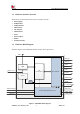
Table Of Contents

Smart Machine Smart Decision
SIM7020G_User Manual_V1.00 6 2019-01-15
Figure Index
Figure 1: SIM7020G block diagram ...........................................................................................9
Figure 2: Pin assignment overview ........................................................................................... 11
Figure 3: Dimensions (Unit: mm) .............................................................................................16
Figure 4: Footprint recommendation (Unit: mm) .....................................................................17
Figure 5: Paste mask SMT stencil footprint outline (Unit: mm)...............................................18
Figure 6: Recommended power supply reference design circuit ..............................................20
Figure 7: Power supply application circuit ...............................................................................22
Figure 8: Reference power on/off circuit ..................................................................................23
Figure 9: Power on timing sequence .........................................................................................23
Figure 10: Power off timing sequence ......................................................................................24
Figure 11: Reference reset circuit .............................................................................................25
Figure 12: UART full modem ...................................................................................................26
Figure 13: UART null modem ..................................................................................................26
Figure 14: Reference circuit of level shift ................................................................................27
Figure 15: TX level matching circuit ........................................................................................27
Figure 16: RX level matching circuit ........................................................................................28
Figure 17: RI behaviour (SMS and URC report) .................................................................28
Figure 18: USB reference circuit ..............................................................................................29
Figure 19: SIM interface reference circuit ................................................................................30
Figure 21: NETLIGHT reference circuit ..................................................................................31
Figure 22:Power on sequence of the VDD_EXT ...................................................................32
Figure 23:Power on sequence of the VDD_3V3 ....................................................................32
Figure 24: SPI interface level conversion reference circuit ......................................................34
Figure 25: Antenna matching circuit (MAIN_ANT) ................................................................37
Figure 26: RF trace should be far away from other high speed signal lines .............................38
Figure 27: The distance between GND to the inner conductor of SMA ...................................38
Figure 28: Top and bottom view of SIM7020G ........................................................................46
Figure 29: The ramp-soak-spike reflow profile of SIM7020G .................................................46
Figure 30: packaging diagram ..................................................................................................48
Figure 32: Tray drawing............................................................................................................49
Figure 32: Small carton drawing...............................................................................................49
Figure 33: Big carton drawing ..................................................................................................50